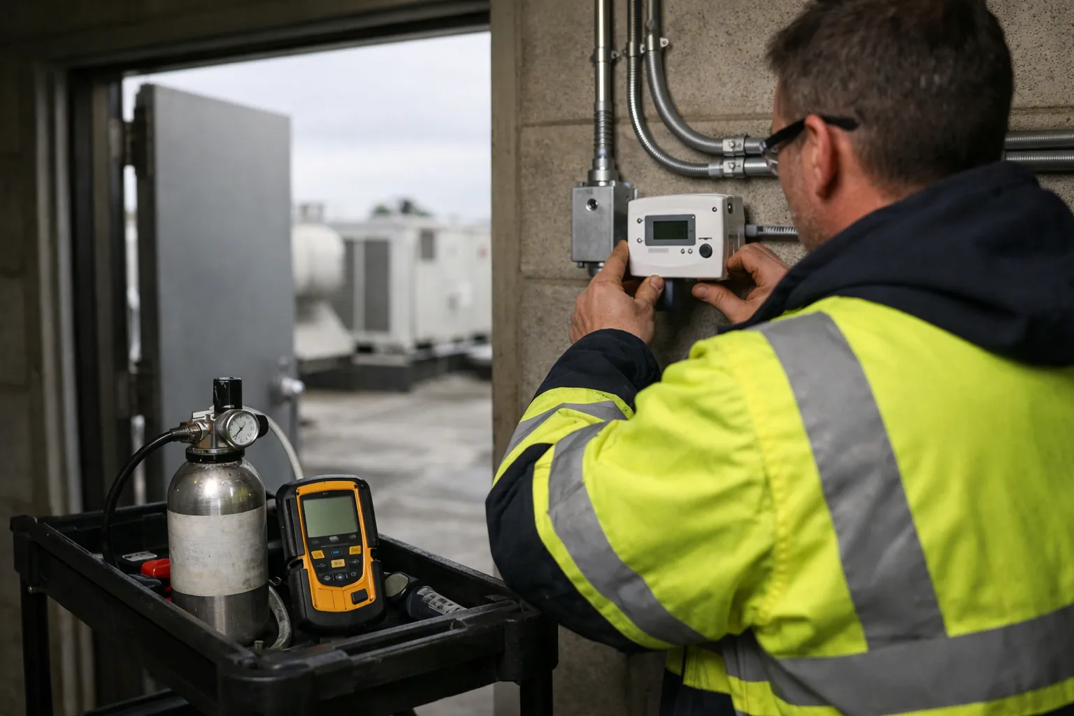
As manufacturers and building owners increasingly adopt lower‑GWP, mildly flammable A2L refrigerants for rooftop units, split systems and heat pumps, reliable refrigerant leak detection has moved from a recommended add‑on to a core safety and compliance requirement. This guide walks HVAC enthusiasts and field teams through a practical, step‑by‑step process to design, install, commission and maintain a permanent refrigerant leak‑detection network tailored to A2L systems in commercial and mixed‑use buildings.
Why a dedicated leak‑detection network matters for A2Ls
A2L refrigerants (mildly flammable blends increasingly used since the early 2020s) reduce climate impact but introduce an element of flammability that affects emergency ventilation, equipment placement, and detection strategy. A purpose‑built detection network does four things:
- Provides early warning at concentrations well below an ignition threshold
- Triggers interlocks (compressor isolation, equipment shutoff, ventilation) automatically
- Reduces downtime and liability by giving service teams actionable alarms and logs
- Helps satisfy local safety codes and insurance requirements when combined with documented procedures
Overview: the design and implementation workflow
- Perform a site risk assessment and inventory refrigerant sources
- Select sensor technologies and alarm architecture
- Plan sensor locations and spacing
- Design electrical and communications integration with the BAS or local alarming system
- Install and wire sensors with consideration for ventilation and environmental protection
- Commission: calibration, bump tests, setpoints and interlocks
- Document, train staff, and schedule maintenance and retest intervals
Step 1 — Site assessment and refrigerant inventory
Start by mapping every point where refrigerant could accumulate or escape:
- Compressors and rack piping
- Service valves, filter driers, brazed joints, and brazing/service panels
- Receiver tanks and oil separators
- Condenser/evaporator coils and coil casings
- Doorways, mechanical rooms, and return plenums that connect to occupied spaces
Document the refrigerant type for each circuit (manufacturer spec sheet), charge size, and whether the refrigerant is heavier or lighter than air. Note ventilation paths and where refrigerant could pool if released. Identify occupant risk areas (machine rooms adjacent to offices, school classrooms above mechanical rooms) and emergency egress paths that could be compromised.
Step 2 — Choose sensor technologies and alarm philosophy
No single sensor type fits every scenario. Typical technologies and use cases:
- Point catalytic (pellistor) detectors — proven for combustible gases; low cost; used where hydrocarbons or some A2Ls are present and ventilation ensures air mixing.
- Infrared (NDIR/open‑path) detectors — open‑path beams across corridors or rooftops detect a gas plume over long runs; useful for equipment rooms and outdoors where point detectors would miss transient plumes.
- Metal‑oxide semiconductor (MOS) and solid‑state refrigerant sensors — many vendors produce refrigerant‑specific point sensors optimized for HFO/HFC/HFO blends; good for detecting halogenated components but performance varies vs. flammables.
- Electrochemical sensors — widely used for toxic gases and some refrigerants; check vendor specs for target refrigerant compatibility.
Best practice: use sensors that detect flammable gases where the refrigerant is classified A2L (or where a hydrocarbon refrigerant is used). When refrigerant blends contain halogenated components that are not combustible, pair a refrigerant‑specific detector with a combustible gas detector for clear coverage.
Step 3 — Sensor siting and spacing (practical rules of thumb)
Follow applicable standards (e.g., national electrical and refrigeration safety codes, EN 378/ASHRAE guidance where relevant) and local authority requirements first. For field design, apply conservative, experience‑based placement:
- Place point detectors within 1–2 m (3–6 ft) of potential leak sources: compressor housings, brazed joints, valve manifolds and service panels.
- If the refrigerant is heavier than air, mount point sensors low (near the floor or duct low points). If lighter, mount higher (near ceiling or return grilles).
- For machine rooms, center sensors and place additional sensors near doors, floor drains and low corners where gas could collect.
- Use open‑path detectors across long equipment rooms, rooftops or duct runs where plume dispersion is likely.
- In occupied zones, avoid placing sensors directly in supply or return diffusers unless the sensor is specified for duct mounting—prefer sensor placement at the room perimeter or mechanical room boundaries.
Typical point detector spacing for small equipment rooms is 3–6 m (10–20 ft) between detectors, but adjust based on room geometry, air movement and leak risk. Document placement with photos and coordinates so future technicians can find them quickly.
Step 4 — Electrical and communications integration
Design for reliable powering and clear alarm pathways:
- Most field detectors run on 24 VAC or low‑voltage DC; confirm manufacturer power requirements and provide supervised power circuits if required by code.
- Define alarm outputs: dry contacts for local shutoffs, relays for BAS input, and digital communications (BACnet MS/TP, BACnet/IP, Modbus, or Ethernet/MQTT) for cloud/analytics platforms.
- Plan for fail‑safe behavior: loss of sensor communication should generate a supervisory alarm and, depending on risk, trigger mitigation steps.
- Isolate alarm wiring and consider use of conduit and weatherproof enclosures on rooftops.
Design interlocks in collaboration with controls and electrical teams so alarms can safely shut compressors, actuate ventilation, release make‑up air, or lock out fuel valves as required.
Step 5 — Installation tips
- Mount sensors to allow easy removal for calibration. Use lockable sensor covers where tampering is a concern.
- Seal conduit entries to avoid false draws or moisture ingress. Use weatherproof housings for outdoor sensors and protect open‑path beams from solar loading and condensation with shields.
- Label each sensor with a unique ID that matches the BAS point naming convention and the site risk matrix.
- Install test ports or sample tubes if using remote sampling systems, and keep sample lines short and heated where condensation is possible.
Step 6 — Commissioning: calibration, setpoints and interlocks
Commissioning is where the design proves out. A field protocol should include:
- Baseline readings with all equipment off and with normal ventilation to record background levels.
- Bump tests for each sensor using manufacturer‑recommended test gas or a calibrated test kit to confirm response.
- Calibration to a known reference gas, and documentation of calibration coefficients and dates.
- Set alarm thresholds expressed as percentages of the Lower Flammability Limit (LFL): common industry practice is a pre‑alarm at ~10% LFL and an evacuation/automatic mitigation alarm at ~25% LFL — but always confirm required thresholds with local codes and system designers.
- Functional tests of all interlocks: simulate a leak alarm and verify compressor isolation, ventilation activation, alarm annunciation in the BAS, and notification to remote monitoring services.
- Log test results, attach photos and wiring diagrams, and produce an as‑commissioned schematic for the maintenance manual.
Step 7 — Operations, maintenance and lifecycle management
A detection network is only as good as its maintenance. Put these items into the operating procedures:
- Daily/weekly: check alarm history in the BAS and verify no recurring nuisance alarms.
- Monthly: perform bump tests to confirm response. Document pass/fail.
- Annual: full calibration against certified gas cylinders or return the sensor to vendor for factory calibration as recommended.
- Replace sensors per manufacturer life expectancy (typically 3–5 years for many electrochemical or MOS sensors; infrared sensors often have longer service lives but require periodic verification).
- Maintain spare sensors and test gas kits on site for quick troubleshooting.
Train building operators and service technicians on alarm response procedures, including immediate actions (isolate compressors, ventilate, clear occupants), troubleshooting, and when to call the vendor or emergency services.
Minimizing false positives
False alarms undermine trust. Reduce them by:
- Selecting sensors with proven cross‑sensitivity profiles and filters tuned to target refrigerants
- Placing sensors away from known nuisance sources (solvents, cleaning agents, vehicle exhaust) or using differential sensing
- Using hysteresis and time‑to‑alarm logic in the BAS to avoid alarms from transient spikes
- Combining detection modalities (a combustible gas sensor plus a refrigerant‑specific sensor) and requiring a second confirmation for critical interlocks
Practical budgeting and procurement
Costs vary widely by sensor type and integration complexity. As a field guide, expect the following ballpark ranges (2026 market context):
- Point combustible gas sensor: $300–$900 each
- Refrigerant‑specific point detector: $500–$1,200 each
- Open‑path infrared detector: $2,000–$8,000 per beam depending on span and weatherproofing
- Integration, wiring and BAS points: budget 25–50% of hardware costs for straightforward projects; more for extensive interlocks and new control panels
Obtain vendor quotes that include calibration kits, spare sensors and documented support for A2L refrigerants; suppliers increasingly publish compatibility matrices in 2024–2026 as A2Ls proliferate.
Compliance and documentation
Always align your design with applicable local and national codes and the recommendations of standards bodies (ASHRAE, ISO, EN) that govern refrigeration safety and gas detection. Maintain a documentation package that includes:
- Refrigerant inventory and Safety Data Sheets (SDS)
- Detector model, serial numbers and calibration records
- Commissioning reports and functional test logs
- Alarm response procedures and contact lists
- One‑line wiring and BAS point mapping
Case vignette — small office RTU retrofit (concise)
Scenario: a small office replaces two R‑410A RTUs with factory low‑charge A2L RTUs on the roof. Risk: rooftop leaks could migrate to a rooftop HVAC chase that feeds the return plenum.
Approach:
- Place two point combustible detectors at roof level—one near each RTU discharge and one in the rooftop chase low point.
- Install an open‑path beam across the chase opening to detect a plume moving along the chase.
- Integrate relays to shut both compressors, enable rooftop make‑up ventilation, and send an alarm to the building operator’s BAS and remote monitoring vendor.
- Commission with bump tests, confirm interlocks, and schedule monthly bump tests plus annual calibration.
Closing checklist — quick field summary
- Inventory refrigerants and identify leak points
- Select sensors appropriate to refrigerant class and environment
- Siting: near leak sources, low/high depending on gas density, open‑path where needed
- Define alarm setpoints in %LFL; confirm with codes and stakeholders
- Wire for supervised power, discrete relays and digital integration
- Commission: baseline, bump tests, calibration, interlock verification
- Document everything; train staff and establish maintenance cadence
Deploying a robust refrigerant leak‑detection network for A2L systems requires a blend of practical field engineering, careful sensor selection, and disciplined commissioning. For HVAC enthusiasts and field crews, following the workflow above will reduce safety risk, limit nuisance alarms, and ensure the system delivers early, actionable alerts—protecting occupants and supporting the industry’s transition to lower‑GWP refrigerants.