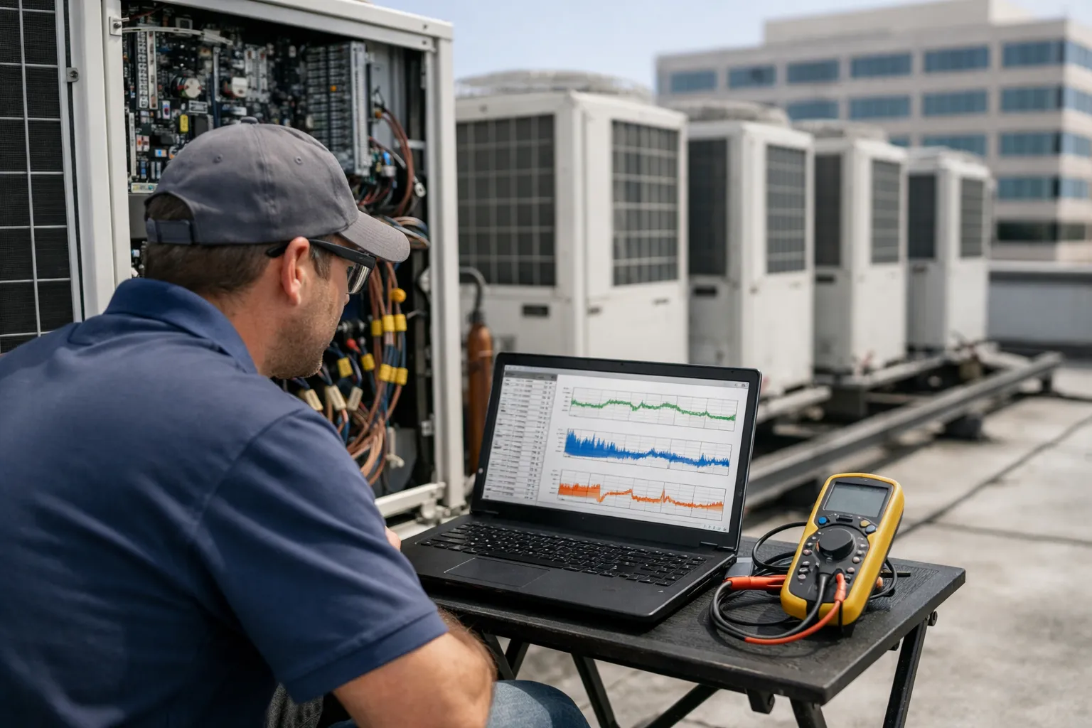
Variable refrigerant flow (VRF) heat‑pump systems dominate many commercial and multifamily HVAC upgrades in 2026. Their modular compressors, inverter drives, and distributed indoor units give energy and comfort advantages — but they also introduce control complexity. Predictive fault detection and diagnostics (FDD) can turn continuous operational data into early warnings that reduce downtime, avoid expensive compressor failures, and optimize refrigerant servicing. This guide walks an HVAC enthusiast through a practical, step‑by‑step FDD deployment for VRF systems using native controllers and open protocols (BACnet/IP, Modbus TCP, MQTT), with commissioning tests and verification strategies.
Why FDD for VRF matters now
VRF systems typically have many distributed sensors and variable‑speed compressors. Faults (refrigerant leaks, EEV malfunctions, airflow restrictions, oil return problems, sensor drift) often appear gradually and are hard to spot in routine service calls. Modern VRF controllers expose a usable set of datapoints and many manufacturers provide APIs in 2026 — making on‑site, lightweight FDD viable without a full cloud migration. A well‑scoped FDD yields:
- Early detection of refrigerant loss and EEV anomalies before capacity loss becomes occupant complaints
- Reduced emergency service calls and avoided compressor failures
- Data to prioritize preventive maintenance and extend equipment life
- Quantified KPIs for energy and reliability improvements
Scope and approach: start simple, validate fast
Pick a single building or equipment bank for your pilot — a small office floor or a single VRF outdoor unit and its associated indoor terminals. Use a phased approach:
- Inventory & data access
- Historic baseline & signature development
- Rule‑based FDD prototype (first iteration)
- Commissioning & simulated faults
- Integration into maintenance workflows and continuous refinement
Step 1 — Inventory: what to monitor
Collect a precise list of available points from the VRF system and controllers. Prioritize points that form the core FDD signals:
- Compressor inverter frequency / VFD speed
- Compressor current (A) and discharge motor temperature
- Suction pressure and discharge pressure (or saturated temps derived from pressure)
- Suction line temperature and liquid line temperature
- EEV (electronic expansion valve) position/command
- Indoor unit supply‑air temp, return/temp sensor, fan speed
- Room temperature and setpoint, thermostat mode
- Outdoor ambient temperature and outdoor unit fan speed
- Alarms/status bits from the native controller (compressor trip, oil return, defrost, communication loss)
Note any missing hardware: if discharge or suction pressure taps aren’t available, derive approximate evaporating temperature using suction line temp sensors plus manufacturer look‑up tables — but flag derived signals as lower confidence.
Step 2 — Data architecture & sampling
Choose a historian that can collect at 1–5 minute resolution for critical points and 5–15 minute for secondary points. Recommended retention: 1 month of 1‑minute data, 12 months of 15‑minute data for trend analysis. Use open protocols — BACnet/IP (ASHRAE Standard 135), Modbus TCP, or MQTT with Sparkplug for edge reliability. Keep cyber hygiene front‑of‑mind (see later).
Sampling guidance
- Compressor current, inverter frequency, pressures, EEV position: 1 min
- Room temps, supply air temps, fan speeds: 1–5 min
- Alarms and status bits: event‑driven plus 1‑min check
Step 3 — Build baseline behavior (signatures)
Collect 2–4 weeks of data under representative operating conditions. Create normalized baselines: relationship of compressor frequency vs load (room delta‑T), suction pressure vs ambient, typical EEV position vs load. Use simple regressions or lookup tables to express "expected" values as functions of ambient and load. Baselines let rules flag deviations rather than fixed absolute thresholds — reducing false positives.
Step 4 — Rule‑based FDD: core detection patterns
Begin with deterministic rule sets — these are transparent and easy to validate in the field. Below are practical rules and signatures that have proven effective for VRF systems. Express each rule as conditions (delta, duration) and confidence level.
Common rule templates
-
Refrigerant leak (slow):
- Conditions: suction pressure trending down >10% vs baseline for 24+ hours AND compressor run time to maintain setpoint increased >15% vs baseline; superheat (suction temp minus saturation temp) trending up >3–5K vs baseline.
- Priority: Medium → High if trend continues 48+ hours.
-
EEV partially stuck/slow response:
- Conditions: commanded EEV position changes by >15% but measured evaporator temp/superheat remains unchanged beyond expected time constant (e.g., 10–15 minutes) OR EEV position saturates near 100% while compressor frequency cannot meet load.
- Priority: Medium.
-
EEV open (flooding risk):
- Conditions: superheat falls >4K below baseline while suction pressure rises >5% and compressor current increases >10%.
- Priority: High if persistent — may require immediate shutdown to protect oil return.
-
Airflow restriction on indoor coil (dirty filter):
- Conditions: indoor supply‑air delta (entering − leaving) reduced >20% with unchanged EEV command and stable ambient; room temp drift up despite increased fan speed command.
- Priority: Medium.
-
Compressor overheating / oil return issue:
- Conditions: discharge temperature above baseline +15–20ºC for >10 min, combined with erratic inverter frequency and reduced capacity.
- Priority: High — alert for immediate inspection.
-
Sensor drift or thermostat mismatch:
- Conditions: room temp diverges from setpoint >3K while indoor unit reports normal airflow and EEV position; cross‑check with independent wired sensor.
- Priority: Low → Medium, verify with handheld measurement.
Keep rules conservative initially (longer durations, higher deltas) to reduce false alarms. Add a graded alert scheme (informational → investigate → critical) so maintenance teams can triage.
Step 5 — Commissioning & fault simulation
Validation is the most important stage. Use manufacturer service tools and on‑site tests to confirm signatures:
- Step test: change room setpoint by ±2–3°C for each zone and observe EEV position, compressor frequency, and pressures. Verify baselines match expected response curves.
- EEV exercise: command fixed open/closed positions and log transient response. Measure time constant and use it in rules.
- Simulated leak: with permission and safe procedures, simulate reduced refrigerant flow by incremental valve restrictions or consult manufacturer test modes; observe signature and confirm detection thresholds.
- Airflow restriction test: partially block return grille to reproduce supply delta changes and validate rule thresholds.
- False‑positive tests: induce benign anomalies (temp sensor disconnects, communication blips) and fine‑tune filters and durations.
Step 6 — Reduce false positives and increase confidence
Common sources of false alarms are transient load swings, occupancy schedules, and commissioning changes. Use these techniques:
- Contextual rules: require anomalies to persist across multiple correlated signals (e.g., both suction pressure and compressor current).
- Time‑window filters: require conditions to hold for a minimum duration (10–60 minutes depending on the metric).
- Rolling baselines: update baselines seasonally or after major control changes.
- Confidence scoring: combine multiple rule triggers into a composite score before raising a critical alert.
Step 7 — Integrate into maintenance workflow
FDD is only useful if defects are fixed. Build a clear workflow:
- Alert → Triage (on‑site verification with handheld gauges and infrared) → Service ticket → Fix → Post‑fix validation test.
- Log each incident with before/after benchmark graphs (suction/discharge, EEV position, compressor current).
- Use technician mobile apps with inline troubleshooting checklists tied to specific FDD rules.
Cybersecurity and data governance
When you pull controller data, follow basic cybersecurity: segregate BMS/VRF networks on VLANs, use TLS and certificate authentication for MQTT, disable unused ports, and adopt strong passwords. Where possible use manufacturer recommended gateways with documented APIs instead of scraping vendor web pages. Keep a data retention and access policy: technicians need operational alerts, but long‑term trend data should be access‑controlled.
KPIs and ROI tracking
Measure outcomes: reduced emergency service calls, compressor failure rate, mean time to repair (MTTR), refrigerant consumption between scheduled services, and energy per delivered ton‑hour. Expect measurable benefits within 6–12 months on properly instrumented systems: fewer emergency calls and fewer premature compressor replacements frequently justify the modest investment in historian and commissioning time.
Common pitfalls and troubleshooting
- Missing signals: don’t build rules around unavailable sensors. If necessary, install low‑cost pressure transducers or clamp meters rather than guessing.
- Overfitting: avoid complex ML models on small datasets. Start with explainable rules and then explore model‑based detection after you have months of labeled events.
- Vendor quirks: different VRF brands expose different scaling, units, and status codes. Normalize units and document mapping carefully.
Next steps and scaling
After a successful pilot, scale by standardizing point lists, rulesets, and commissioning playbooks. Move to hybrid approaches: keep deterministic rules as the first tier and add supervised ML classifiers that use labeled historical faults for higher sensitivity. Maintain an evidence library of fault signatures and technician notes — it becomes more valuable over time.
Predictive FDD for VRF systems is achievable today using native controllers and open protocols, with conservative, well‑tested rule sets and solid commissioning. For HVAC enthusiasts and small contractors, the path is clear: start with a focused pilot, instrument the right points at sufficient resolution, validate rules with on‑site tests, and integrate alerts into routine maintenance. The result: fewer surprises, longer equipment life, and tangible savings.
Appendix: Quick commissioning checklist
- Inventory points and confirm units expose them via BACnet/Modbus/MQTT
- Implement historian, sample critical points at 1 min
- Collect 2–4 weeks baseline data during representative occupancy
- Implement 6–8 core rule templates (see guide)
- Conduct step tests and simulated faults; tune thresholds
- Deploy alerts with priority levels; integrate into ticketing
- Run quarterly revalidation and update baselines seasonally