Introduction
What you will learn: an updated, practical workflow for ultrasonic refrigerant leak detection (USD) and repairs tailored to commercial HVAC through August 2026. This guide is for HVAC technicians, facility maintenance leads, and systems‑minded enthusiasts who perform or supervise leak surveys. It updates techniques, tools and safety guidance to reflect growing use of lower‑GWP and mildly flammable refrigerants (A2L), advances in ultrasonic and acoustic imaging hardware and software, and modern digital recordkeeping practices.
Why this matters: refrigerant costs and regulatory scrutiny remain high, and many owners now track refrigerant use as an operational KPI. Faster, more reliable leak localization plus compliant repair and documentation saves operating expense, reduces greenhouse gas emissions, and minimizes risk from newer refrigerants.
Prerequisites and context
- Knowledge & certification: Technicians must hold the appropriate refrigerant handling certification for their jurisdiction (for example, EPA Section 608 in the U.S.) and receive manufacturer training for A2L refrigerants where applicable.
- Regulatory backdrop: The Kigali Amendment and subsequent national phasedown policies continue to increase price and supply pressure on high‑GWP HFCs, accelerating adoption of low‑GWP and A2L options (e.g., R‑454B, R‑32, R‑1234yf variants in select systems). Expect site‑specific safety rules for A2L handling and brazing.
- Operational context: Ultrasonic detection remains most effective when systems are at or near operating pressure; however, new complementary tools (acoustic imaging cameras, drone‑mounted sensors, and AI noise filtering) make surveys faster in complex sites.
Tools and consumables — 2026 update
In addition to the classic kit (ultrasonic detector with probes, electronic sniffers, nitrogen, recovery machines, PPE), include these 2026‑era essentials:
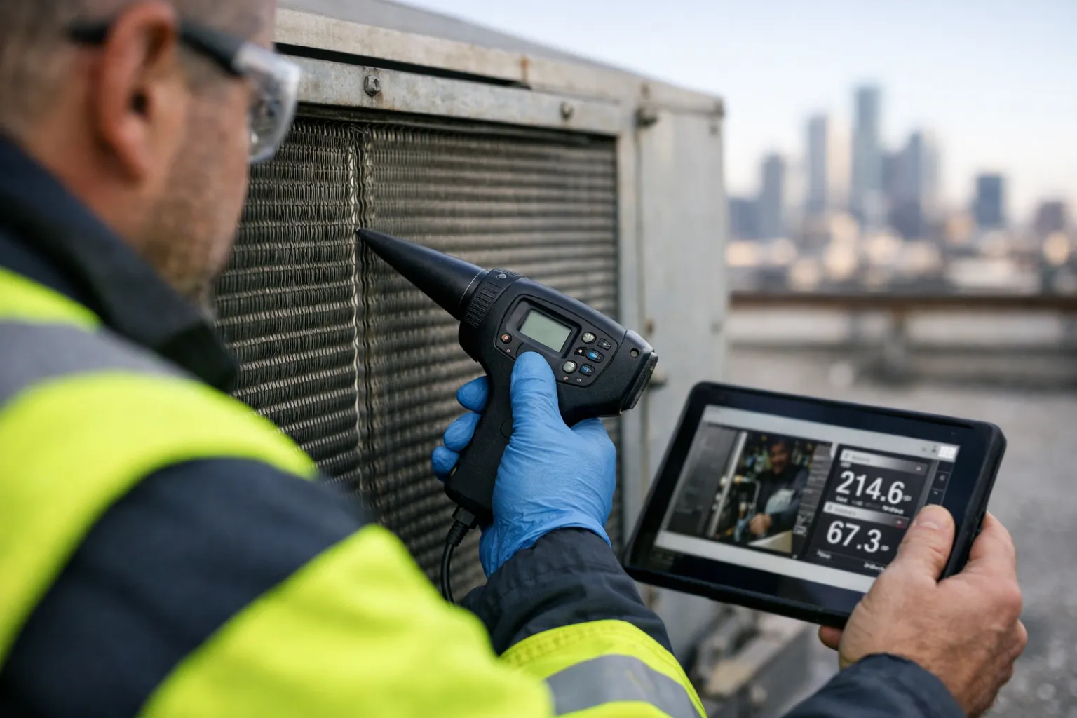
- DSP ultrasonic detectors with digital signal processing, selectable frequency bands and Bluetooth/GPS tagging for automated mapping.
- Acoustic imaging cameras (array microphones) — useful for quick scans of large condensers and multiple parallel lines where pinpointing with a handheld probe is slow.
- Drone platform with ultrasonic or acoustic sensor option for large rooftop arrays or hard‑to‑access piping runs (verify site and insurer permissions first).
- Integrated CMMS/mobile apps: QR/asset tag readers, photo capture, pressure and dB metadata upload, plus automated PDF report generation for owner sign‑offs.
- Dual confirmation detectors: heated‑diode/infrared ppm detector plus a newer tunable‑laser or photoacoustic instrument when you need more quantitative sensitivity for very small leaks.
- UV dye updated guidance: lower‑solubility dyes are available for some new oils; follow manufacturer approval to avoid warranty issues.
Pre‑survey planning (30–90 minutes)
- Gather system facts: refrigerant type(s), last charge mass, service history, system diagrams, and any prior recurring leak sites. Why: knowing whether a system uses an A2L refrigerant changes safety and repair sequencing.
- Check codes & manufacturer requirements: review local code changes since 2024 (ventilation, brazing restrictions with A2L, hot‑work permits). Why: noncompliant repairs can void warranties or create liability.
- Coordinate timing: schedule when noise and customer impact are minimal. For systems with intermittent load‑dependent leaks, plan to survey during the operating condition that produces the leak (peak cooling or heating).
- Assemble digital assets: create a job in your CMMS with QR tags for the system, preload typical forms, and confirm detector batteries, spare probes, and PPE. Why: immediate documentation reduces repeat visits and dispute risk.
Step‑by‑step ultrasonic survey (field workflow)
Field technique still determines success. Use a documented, repeatable approach — pattern, pace and confirmation.
- Baseline visual pass (10–20 minutes):
- Look for oil streaks, frost, corrosion, loose fittings and damaged insulation. Photograph with scale and asset QR visible.
- Flag high‑risk components: service ports, filter driers, brazed joints, valve stems, and compressor fittings.
Why: visual cues reduce time spent chasing false positives from ambient ultrasonic sources.
- Get the circuit under pressure if safe (run or charge):
- Operate the system to normal pressures. For removed components or de‑energized systems, apply dry nitrogen within allowed test limits. Follow A2L hot‑work/ventilation rules.
Why: ultrasonic emissions are pressure dependent; many leaks are only audible under normal operating pressures.
- Initial scan with broad sensor or acoustic camera:
- Use an acoustic imaging camera or the detector’s parabolic probe to rapidly scan coils and long line sets from 1–5 m. Mark suspect zones in the CMMS map with GPS or QR tag.
Why: fast area scans identify candidate regions where closer handheld probing is warranted.
- Pinpoint with directional and stethoscope probes:
- Move from low to high sensitivity to avoid saturation. Sweep slowly (10–30 cm/s) and stop where the dB/frequency spike maximizes. Use the stethoscope probe to triangulate exact joint or hole.
Why: controlled approach reduces false leads and provides repeatable location data.
- Confirm with secondary meters and visual aids:
- Use an electronic ppm detector close to the pinpoint to confirm refrigerant presence. If leak is intermittent, apply UV dye per manufacturer instructions and schedule a follow‑up inspection under UV light.
- For very tight systems or inaccessible aluminum microchannel coils, arrange tracer gas (helium) with a mass spectrometer if onsite methods fail.
Why: USD is a localization tool, not a quantifier — secondary confirmation is essential for repair decisions and reporting.
- Record everything:
- For each finding capture: photo with QR and scale, dB/frequency reading, ppm reading (if any), ambient noise description, operating pressure and timestamp. Upload to CMMS immediately.
Why: detailed records reduce disputes and support leak‑rate tracking over time.
Documenting and triaging leaks
Use a consistent severity scale and action matrix:
- Minor: no oil staining, low or no ppm at 10 cm, slow charge loss — recommendation: monitor and schedule repair within regular maintenance.
- Moderate: oil staining or measurable ppm close to source, detectable pressure loss — recommendation: plan same‑week repair; evaluate need for replacement parts.
- Critical: visible holes, rapid pressure loss or risk to occupants (A2L pooling, odour) — recommendation: shut down and immediate repair following emergency procedures.
Prioritize by refrigerant cost, system criticality (data centers, OR suites), and safety exposure. For mission‑critical systems, consider temporary containment (service loop and throttle adjustments) only as documented stopgaps.
Repair workflow (safety first) — updated for A2L and modern practice
- Isolate, recover and label: Recover refrigerant using certified equipment and scales. For A2L systems, follow manufacturer and local codes for ventilation and bonding. Label recovered refrigerant and record mass changes in the job file.
- Pressure test with dry nitrogen: After recovery, pressure test to manufacturer‑specified test pressure. For brazing, use a nitrogen purge to prevent internal oxidation. For A2L systems, ensure adequate purge and test pressure limits per code.
- Repair method selection: Prefer permanent methods:
- Brazing with nitrogen purge for copper lines (technician must use brazing processes approved for the refrigerant and lubricant in the system).
- Component replacement for valve cores, access fittings, service valves or coils. For aluminum microchannel coils, assess shop‑level repair vs. replacement.
- OEM approved repair kits for coils when available; verify warranty impact and manufacturer sign‑off.
- Evacuate and validate: Pull vacuum to manufacturer spec (commonly 500 microns for new circuits). Hold vacuum for the recommended duration, then backfill and leak‑test again using USD and electronic detectors.
- Recharge and performance verification: Recharge to specified mass using scales and perform subcooling/superheat checks. Run performance cycle and document operating pressures, temperatures and any abnormal vibration or noise.
- Follow‑up monitoring: For critical repairs, schedule a 24–72 hour follow‑up scan and a 30‑day check. Upload follow‑up results to the CMMS and mark any repeat failures for engineering review.
Post‑repair validation and recordkeeping (2026 best practice)
Complete, structured documentation is now expected by many owners and insurers:
- Deliver a concise owner report: initial findings, repair actions, final charge, date/time stamps and technician sign‑offs.
- Log cumulative refrigerant mass lost and leak rate estimates in the asset history (helpful for lifecycle cost modeling and replacement decisions).
- Apply a QR/ID tag at the repair site with a link to the full job record to speed future inspections.
Common mistakes and how to avoid them
- Skipping secondary confirmation: USD can pinpoint noise sources that are not refrigerant. Always verify leaks with a ppm detector or visual evidence before opening a system.
- Improper A2L hot work: Ignoring updated hot‑work rules for A2L refrigerants risks fire or regulatory action. Obtain permits, ventilate and use gas monitoring when brazing.
- Poor documentation: Incomplete photos, missing pressure readings or no timestamp can lead to disputes. Use mobile CMMS uploads at-the-time-of-service.
- Overreliance on temporary patches: Epoxy and clamps are short‑term fixes; document them and plan full repair to prevent repeat visits.
- Ignoring ambient ultrasonic noise: HVAC equipment, wind and mechanical bearings create ultrasonic signals. Use DSP settings and confirm with a stethoscope probe.
Pro tips
- Use an acoustic camera to triage large rooftop banks — it reduces man‑hours for initial localization by up to 50% on multi‑unit roofs (field reports from integrators).
- Map leak locations to a building floor plan with GPS/QR metadata — trend analysis over 12–24 months identifies chronic problem areas that benefit from retrofit or replacement.
- For intermittent load‑dependent leaks, instrument the system to record pressures and temperatures during peak hours and schedule a targeted follow‑up survey.
- Train junior techs on two skills: the audible signature of compressor bearings vs. refrigerant hissing, and how to run the detector in both time and frequency modes (where available).
Example workflow timeline and labor estimate (updated)
Small commercial RTU with coaxial piping (single unit):
- Pre‑survey planning & mapping: 30–60 minutes
- Acoustic camera scan + handheld USD confirmation: 45–90 minutes
- Recovery, isolation and nitrogen pressure test: 1–2 hours
- Repair (brazing or component swap) and pressure test: 1–3 hours
- Evacuation, recharge and validation: 1–2 hours
- Documentation & owner report: 30–45 minutes
Total: typically 5–9 field hours for an accessible rooftop unit; complex systems, A2L protocols or coil swaps increase time.
When to escalate: advanced diagnostics
- Use helium tracer with mass spectrometry for sub‑ppm sensitivity on shop‑removed coils or sealed assemblies.
- Remove suspect coils for vacuum decay testing when in‑place diagnosis is inconclusive.
- Replace coil assemblies when repeat repairs occur or when repair risk exceeds replacement cost (document decision rationale).
Final thoughts
Ultrasonic leak detection remains a rapid, reliable first line for HVAC refrigerant management in 2026. The step forward since 2024 has been integration: acoustic imaging for speed, DSP and AI filtering for accuracy, drones for access, and digital CMMS workflows for traceable outcomes. Combine these tools with proper A2L safety processes and consistent documentation to reduce refrigerant loss, operating cost and regulatory risk.
FAQ
Are ultrasonic detectors reliable with A2L refrigerants?
Yes — ultrasonic detection senses the acoustic emission from pressure escaping an orifice, independent of refrigerant chemistry. However, A2L systems require modified safety steps during pressurization, brazing and recovery. Always confirm ultrasonic localization with a ppm detector and follow manufacturer and local code guidance for A2L handling.
When should I use an acoustic imaging camera instead of a handheld USD?
Use acoustic imaging for rapid triage on large condensers, multiple-parallel lines, or when multiple units are close together (e.g., rooftop fields). Handheld probes remain the best tool for final pinpointing and verification near fittings and valves.
Can drones replace physical inspections for rooftop leak surveys?
Drones with mounted acoustic or thermal sensors can greatly reduce time and risk on large, hard‑to‑access rooftops. They do not replace handheld confirmation for final repairs. Prior to drone use verify site permissions, insurer rules, and that the drone payload provides sufficient sensor sensitivity for your target leak sizes.
How often should a preventive ultrasonic survey be scheduled?
Schedule surveys based on system criticality and historical leak behaviour: mission‑critical plants quarterly or semi‑annually, typical commercial RTUs annually or biannually supplemented with post‑major‑service scans. Use recorded leak‑rate trends to adjust cadence.
What documentation will protect me and the owner if a leak reappears?
Comprehensive, timestamped documentation: photos with scale and QR tag, operating pressures, detector dB and ppm readings, repair method details, and follow‑up checks. Upload these to a CMMS and include a signed owner report. This trail is critical for warranty claims, regulatory compliance and insurance purposes.