
There is a discreet luxury in a house that simply behaves: the study stays serene while the sun glares on the west façade, guests sleep in comfort without the rest of the home overcooling, and the upstairs corridor never becomes a pressure‑driven wind tunnel. Zoning a ducted HVAC system is the engineering approach that creates that steadiness—when it’s done right. Done poorly, it’s expensive trouble.
This June 2026 update is for HVAC enthusiasts, high‑performance builders, and meticulous homeowners who want zoning guidance that reflects current equipment, control standards, and commissioning expectations. You’ll get actionable steps to decide when zoning is warranted, how to draw zones that behave, what to check in ducts and equipment, how to pick dampers and controls that respect modern inverter systems, and how to commission for comfort, efficiency, and quiet operation.
Prerequisites and context (what to know before you draw zones)
- Zoning is a systems solution, not an extra thermostat. True ducted zoning uses motorized dampers controlled by a zoning controller that coordinates blower speed and outdoor unit modulation.
- Airflow and static pressure are the metrics that live or die by zoning. Most residential air handlers are designed for a total external static pressure (TESP) around 0.5 in. w.c.; each damper adds resistance to that budget. Minimum airflow requirements (often in the 350–400 CFM/ton range depending on manufacturer) must be preserved.
- Load difference drives the business case. Zoning is defensible where zones have persistent, substantive differences in solar gain, envelope quality, orientation, or occupancy schedule.
- Manual J, S, and D remain your baseline. ACCA’s Manuals J, S, and D are still required for predictable results. Use them to translate comfort needs into airflow and duct sizing objectives.
- Market and tech context in 2026: Variable‑capacity heat pumps and inverter air handlers are standard in high‑efficiency installs. Controls have matured: open‑protocol integration (Matter, BACnet over IP, Modbus) and grid‑interactive features are common. Those capabilities raise the upside for zoning but add integration complexity that must be planned.
Reality check: Zoning does not hide poorly sized or leaky ducts. It reveals them.
Step 1: Decide if zoning is the right tool (or if balance is enough)
- Clarify the comfort problem you are solving.
- Afternoon‑southwest solar load in a great room while bedrooms remain cool.
- Finished attic/over‑garage space that needs conditioning after the main house is satisfied.
- A home office used continuously while the rest of the house can drift several degrees.
Why: Zoning should directly address a measurable, recurring thermal mismatch. Don’t zone to paper over envelope or distribution faults.
- Evaluate simpler, higher‑ROI fixes first.
- Air sealing and targeted insulation (attic and rim joists are high impact).
- Supply/return balancing, register selection, and fan speed tuning.
- Corrected return paths, added transfer grilles, or a single extra return duct.
- Targeted duct repair and sealing (mastic or aerosol sealing).
Why: These are less costly and often eliminate the need for zoning.
- Score the home’s zoning fit. Zoning typically succeeds when:
- Equipment can modulate (variable‑speed blower + inverter outdoor unit).
- There are natural trunk branches for damper placement.
- Space exists for returns or transfer paths for closed zones.
- Minimum airflow can be satisfied in the smallest likely single‑zone call.
Why: If the smallest zone cannot accept required airflow, the system will produce high static pressure, noise, or short cycling.
Step 2: Map comfort priorities and define predictable zones
- Use a conservative zoning pattern. For many houses, a practical layout is:
- Zone 1: Main living areas (kitchen, family room, dining)
- Zone 2: Sleeping wing(s)
- Zone 3: Bonus/problem area (sunroom, finished attic, guest suite)
Why: This pattern reduces single‑zone calls that fall below minimum airflow.
- Avoid micro‑zoning unless engineered. Room‑by‑room zoning often creates tiny single‑zone calls that a ducted system cannot accommodate. For room‑level control, compare costs and quality of VRF/mini‑splits, fan‑powered terminals, or purpose‑built residential VAV solutions.
- Group rooms by load profile, not convenience. Combine rooms with similar solar exposure, envelope quality, and occupancy schedule so a zone behaves predictably.
- Plan returns per zone. Each closed zone needs a reliable return path: dedicated return grille, sized transfer grille or jump duct, or a combination. Door undercuts rarely suffice in tight, modern construction.
Step 3: Verify loads and airflow so minimum system airflow is always met
- Do room‑by‑room Manual J and convert to design airflow. Don’t accept rules of thumb. Manual J outputs should be translated into design CFM targets for each zone and the minimum single‑zone scenario.
- Identify the minimum‑open zone scenario and verify CFM. The smallest zone that may call alone needs the airflow to keep the coil and blower within manufacturer minimums—typically 350–400 CFM/ton for many heat pumps, but always confirm with equipment literature.
- Match equipment limits and protections. Confirm minimum CFM, acceptable TESP, and coil entering air temperature protections from the air handler and outdoor unit. Modern inverter systems can modulate down but still require a minimum airflow to avoid control or defrost problems.
Step 4: Evaluate ductwork and static pressure (the make‑or‑break step)
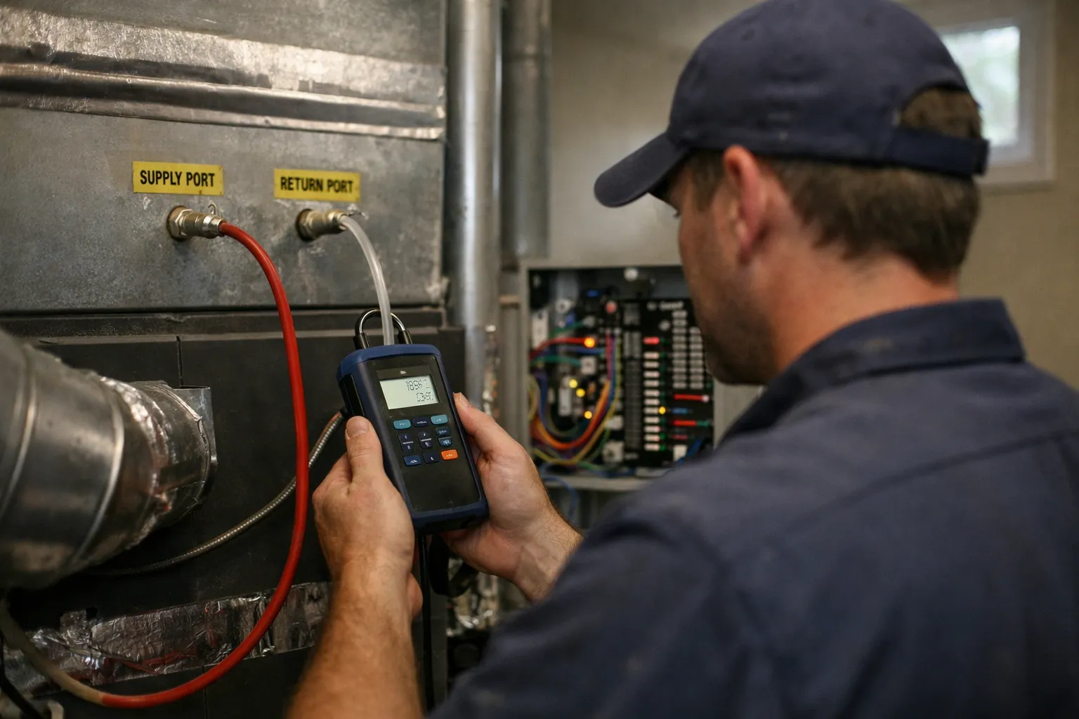
- Measure TESP and leakage on existing systems. Field measurement with a manometer and a duct‑blaster test where possible are essential diagnostics. Many residential air handlers are rated near 0.5 in. w.c. TESP; keep your zoning additions within that budget.
- Inspect trunk layout for practical damper locations. Dampers should control entire branches rather than individual flex runs unless the branch is engineered and accessible.
- Confirm return path capacity and low pressure drop. Restrictive returns are a dominant failure mode. Returns must be able to accept conditioned air when zones close without creating large negative/positive pressures in living spaces.
- Prioritize sealing and insulation. Duct leakage in unconditioned spaces undermines zoning benefits. Where feasible use aerosol duct sealing for large attic distributions and mastic at connections.
Step 5: Choose dampers and fail‑safe strategies
- Pick damper type by duct geometry and modulation needs. Round blade dampers for round trunks; opposed‑blade dampers for rectangular trunks where finer modulation and lower leakage are required. Specify low‑leakage dampers for sensitive zones.
- Decide fail‑safe positions thoughtfully. Defaulting a zone to open on power loss prevents frozen coils and maintains building pressure; in some mechanical closets you may want normally closed—but document risk and protections.
- Provide service access and spare parts. Include removable access panels and note actuator model numbers and power specs in the service documentation.
- Plan for actuator noise and movement damping. Select actuators with soft‑start/stop or add mechanical dampers to prevent thumps in quiet living spaces.
Step 6: Maintain minimum airflow—let equipment modulate, pick a dump zone, or use controlled bypass
- Prefer intelligent blower modulation. The best outcome is variable‑capacity equipment that reduces fan speed and compressor capacity on small calls—preserving coil performance and lowering noise.
- Design a relief or “dump” zone where practical. A large common area with generous returns serves as a predictable place for excess airflow when other zones close—better for dehumidification than many bypass strategies.
- Only use a bypass when actively controlled. An uncontrolled bypass can degrade dehumidification and cause comfort drift. If you employ a bypass, control it with a static‑pressure transducer and closed‑loop logic so TESP stays near the target and latent performance is preserved.
- Leverage static sensors and PID control where possible. In 2026, inexpensive differential pressure sensors and controllers allow closed‑loop control of bypass dampers and fan speed—bringing residential systems closer to commercial VAV behavior without mystery.
Step 7: Select controls and thermostats that match the equipment—and the homeowner
- Choose a zoning controller compatible with inverter equipment. Many manufacturers publish communicating zoning modules that preserve modulation. If you use off‑the‑shelf 24V controllers, confirm they won’t force an inverter system into single‑stage behavior.
- Consider grid‑interactive capability as an option. Utilities and incentive programs increasingly reward load flexibility. Design controllers with optional DR participation and local override so the homeowner can opt in without sacrificing comfort.
- Prefer open protocols and integration-ready devices. Controllers offering BACnet/IP, Modbus, or Matter/UPnP make future integration with home energy management systems easier for owners who want visibility into performance.
- Place sensors where they tell the truth. Avoid direct sun, register throw, exterior doors, and obvious heat sources. Add humidity sensors in humid climates or basements, and consider door‑position sensors to flag user behaviors that defeat zoning logic.
- Set sensible deadbands and anti‑short‑cycle logic. Tight settings create damper hunting and audible irritation. A calm control strategy improves perceived luxury, reduces wear, and saves energy.
Step 8: Commission the zones—measurement and documentation beat hope
- Measure airflow and static pressure with each zone calling independently. Commissioning should include:
- TESP measurements
- Delivered CFM per zone using a flow hood or calibrated meter
- Supply and return temperatures and ΔT under load
- Acoustic checks at registers and dampers
- Validate control logic and equipment protections. Confirm freeze protection, compressor staging, and defrost behavior during single‑zone calls. For inverter systems, ensure the controller preserves modulation capability.
- Document and hand over a concise commissioning report. Include measured TESP, CFM per zone, damper positions, controller setpoints, and recommended maintenance intervals. Treat it as the specification for future service.
- Include acoustic remediation where necessary. If registers whistle or dampers thump, fix them during commissioning—sound is as important as temperature in high‑end installations.
Common mistakes (and what they cost you)
- Zones that are too small. Result: high static pressure, noise, short cycling, and higher fan energy.
- Ignoring return air. Result: poor comfort, infiltration, and humidity problems.
- Uncontrolled bypass ducts. Result: reduced dehumidification and unpredictable comfort.
- Mismatching modern inverter equipment with legacy controls. Result: robbed efficiency and compromised modulation.
- No damper access. Result: invasive, expensive repairs and extended downtime when actuators fail.
Pro tips for a smoother, quieter, more efficient zoning system
- Design around the minimum‑airflow scenario. Make the smallest single‑zone call work first—everything else is easier after that.
- Fix the worst envelope problem first. Reducing load in a problem room often reduces zoning complexity and equipment stress.
- Use transfer grilles and jump ducts thoughtfully. They’re unglamorous but frequently the difference between a composed system and a temperamental one.
- Insist on measured TESP and a commissioning report. Treat the commissioning report as the system’s spec sheet for future service and resale value.
- Plan humidity control explicitly. In humid climates, partial‑load operation can undermine latent removal. Pair zoning with variable‑capacity equipment, dedicated dehumidifiers, or control strategies that preserve coil load and ΔT across scenarios.
- Think about integration and future upgrades. Specify controllers that allow firmware updates, open‑protocol telemetry, and optional participation in utility incentive programs—so the system can gain features without invasive hardware swaps.
FAQ
How many zones are “too many” for a typical residential ducted system?
For most homes, 2–4 well‑sized zones are the practical sweet spot. More zones increase the risk of hitting minimum‑airflow and static‑pressure limits unless the equipment and ducts are engineered for small‑zone operation or you choose VRF/mini‑split alternatives.
Do I need a bypass duct for zoning?
Not necessarily. Modern inverter equipment and a reasonable relief zone often maintain safe airflow without a bypass. If you do use a bypass, control it by static pressure with closed‑loop logic and include commissioning to prevent dehumidification loss and excess fan energy.
Can zoning fix a hot upstairs?
Sometimes—but confirm basics first: attic insulation and air sealing, adequate returns, and sufficient supply duct size to the upstairs. Zoning manages differing loads but can’t overcome grossly undersized ducts or major envelope deficiencies.
Will zoning reduce energy use?
Zoning can reduce energy use when it reduces conditioning of unoccupied areas and is paired with modulating equipment that runs efficiently at lower outputs. Poorly designed zoning can increase fan energy and cycling and negate savings.
What paperwork should I insist on from my contractor?
Ask for room‑by‑room Manual J loads, a Manual D duct plan, measured TESP before and after installation, and a commissioning report with per‑zone CFM and static pressures during single‑zone calls. Also request equipment minimum CFM and controls compatibility in writing.
Reference framework: This guide follows ACCA Manuals J, S, and D and established field practices for static‑pressure and duct‑leakage testing. It also reflects 2026 trends toward inverter heat pumps, communicating controls, and increased emphasis on commissioning and grid‑aware systems.