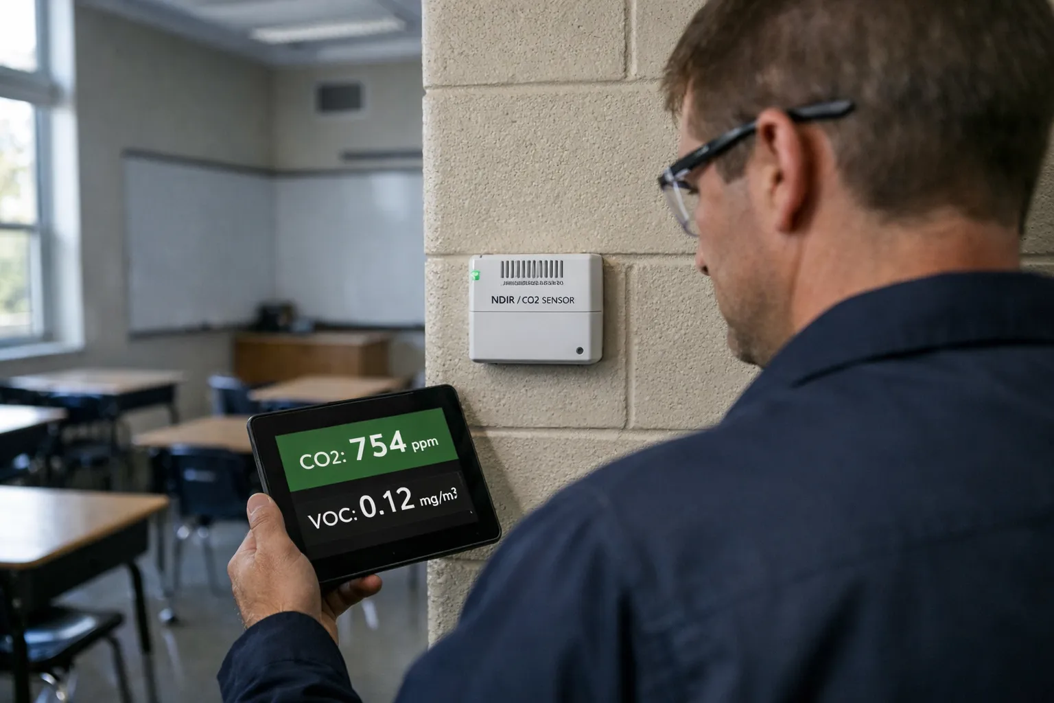
Demand‑controlled ventilation (DCV) using CO2 and VOC sensing is one of the most cost‑effective ways schools can improve indoor air quality while reducing energy use. This guide walks HVAC enthusiasts through a practical, field‑ready process for designing, integrating and commissioning CO2+VOC DCV systems in K‑12 classrooms and support spaces. It focuses on actionable decisions—sensor selection and placement, control logic, BMS integration, airflow verification, energy calculation and commissioning checks—that produce repeatable, measurable outcomes.
Why CO2+VOC DCV for K‑12?
Classroom occupancy varies widely throughout the day (class changes, assemblies, after‑school programs). Fixed ventilation sized for peak occupancy wastes energy most of the time. DCV reduces outdoor air (OA) when spaces are lightly occupied and increases OA when people are present and ventilation demand rises.
- CO2 is a reliable proxy for human occupancy and respiration; controlling to a CO2 threshold keeps per‑person ventilation near target.
- VOC sensing (TVOC or specific compounds) catches odor/contaminant events that CO2 misses—cleaning, art classes, science lab odors, bathroom exhaust failures.
- Combined CO2+VOC control improves occupant comfort and helps maintain IAQ targets while minimizing unnecessary heating/cooling of OA.
Where DCV Is Appropriate
DCV is well suited to classrooms, cafeterias, multipurpose rooms and gymnasiums that have varying occupancy. Avoid using DCV where pollutant sources are unrelated to occupancy (chemical storage rooms, certain labs), or where regulatory minimums require constant minimum ventilation.
Standards & Regulatory Context (2026)
Design and commissioning should reference the latest ASHRAE standards and local codes—ASHRAE 62.1 (ventilation for acceptable IAQ) remains the engineering baseline for non‑residential ventilation. Local jurisdictions or school districts may have specific requirements (minimum OA rates, maximum CO2 setpoints). As of 2026, many districts are adding IAQ requirements to building specifications and maintenance contracts, and procurement of CO2/VOC sensors has become routine in capital and retrofit budgets.
Step‑by‑Step Design and Implementation
1. Establish performance targets
Decide measurable IAQ and energy targets up front:
- Target CO2 setpoint(s): common practice is to control to ≤800–1000 ppm (indoor) as a primary target; set a hard alarm at ≥1200 ppm.
- Minimum OA: never reduce below the code or ASHRAE‑required minimum outdoor air rate for the space.
- VOC action levels: define thresholds for warning and for increased OA; use manufacturer guidance and local IAQ policy to set those limits.
- Energy goal: expected OA reduction and projected HVAC energy savings per year (use the method in “Estimating Energy Impact” below).
2. Choose sensors and sampling strategy
Sensor choice materially affects DCV performance.
- CO2 sensor type: Non‑Dispersive Infrared (NDIR) sensors are standard—select units with measurement range 0–5,000 ppm and accuracy ±(30–50 ppm + 3% reading).
- VOC sensor type: PID (photoionization detector) for broad VOC sensitivity and lower detection limits; MOS (metal oxide) sensors are lower cost but show more drift and cross‑sensitivity. Avoid relying on eCO2 (CO2 estimates derived from VOC sensors) as a CO2 substitute.
- Sensor features: digital output (Modbus, BACnet MS/TP or IP), built‑in temperature/humidity compensation, field‑calibration capability, tamper‑resistant mounting, and documented drift/maintenance schedule.
- Sampling strategy: one CO2 sensor per typical classroom; for large open spaces (auditorium, cafeteria), use multiple sensors spaced to represent occupancy zones. VOC sensors can be sited in representative problem areas (near art rooms, cafeterias) or co‑located with CO2 in general‑purpose zones.
- Mounting: wall‑mounted at breathing zone height (0.9–1.8 m / 3–6 ft), away from windows, doors, supply diffusers and direct occupant exhalation (not directly over student desks or teacher’s head).
3. Control logic and BMS integration
Clear, simple control logic reduces failures in the field. Integrate sensors into the building automation system (BMS) where possible; otherwise use local controllers with BACnet or Modbus output.
- Maintain a minimum OA flow based on code/ASHRAE regardless of sensor readings.
- Primary control variable: CO2 level. Use a proportional control law (PID or linear proportional band) to modulate OA damper or VAV minimum setpoint to maintain CO2 below setpoint.
- Supplemental VOC logic: if VOC ≥ warning threshold, increase OA to a defined high‑ventilation limit for a fixed purge period; if simultaneous CO2 is high, prioritize CO2 to avoid negative pressurization.
- Anti‑oscillation: implement deadband/hysteresis (e.g., ±50 ppm) or time‑based averaging (1–3 minutes) to avoid frequent actuator movement.
- Economizer coordination: when economizer is active and OA temperature permits, allow OA to satisfy ventilation demand; ensure DCV does not disable economizer function.
- Fallback mode: on sensor failure or loss of communications, revert to fixed minimum ventilation and raise an alarm for maintenance.
4. HVAC impacts—fans, filters, pressurization
Before deployment verify that fans can handle variable OA fraction and increased heating/cooling load during peak purge events. Check filter pressure drop and static reserves, and confirm that pressurization relationships (corridor vs classroom) remain acceptable across OA modulation.
5. Commissioning and verification
Commissioning must validate the end‑to‑end behavior of sensors, controls and airflow. Key steps:
- Pre‑installation survey: document existing ventilation rates, schedules and OA damper capability.
- Sensor functional test: verify power, communications, zero/span calibration where applicable.
- CO2 decay test to confirm effective ventilation rate. Use the decay formula: n = −(ln[(C(t) − C0)/(Cinit − C0)])/t where n is air changes per hour, C0 is outdoor CO2, Cinit is initial indoor CO2 and C(t) is concentration after time t. Perform tests with space unoccupied or with known occupant exit.
- Balometer or tracer‑gas tests to verify OA flow against design/minimum.
- Functional sequence test: with the room occupied, raise CO2 by typical occupancy and observe OA damper/ VAV response; validate VOC trigger by a controlled, safe VOC release (e.g., marker fumes) if allowed by protocol.
- Data logging: record CO2, VOC, OA damper position, supply airflow and temperatures continuously for at least one week of representative school operation.
- Documentation & training: provide sequence of operations, sensor locations, calibration schedule and troubleshooting guidance to facilities staff.
Estimating Energy Impact (Quick Method)
To estimate annual HVAC energy change from DCV, compute avoided OA heating/cooling load from reduced OA flow during unoccupied/lightly occupied hours.
Basic instantaneous load equation:
Q = ρ × Cp × V × (Tout − Tind)
- ρ = air density (~1.2 kg/m³)
- Cp = specific heat (~1.006 kJ/kg·K)
- V = OA volumetric flow change (m³/s)
- Tout − Tind = outdoor minus indoor temperature (°C)
Integrate Q over the annual hours when DCV reduces OA. Convert to kWh (1 kWh = 3.6 MJ) and account for HVAC equipment efficiencies. Example (simplified): reducing OA by 200 cfm (~0.0946 m³/s) for 6 hours/day over a 180‑day school year with average winter delta T of 15°C yields roughly:
Q_inst ≈ 1.2×1.006×0.0946×15 ≈ 1.71 kW; energy ≈ 1.71×6×180 ≈ 1,846 kWh (raw), then divide by system heating efficiency to get fuel/electric equivalence.
Run this calculation for heating and cooling seasons, and include fan energy impacts from any additional damper or VAV movements.
Practical Example (Classroom)
Assume a 900 ft² classroom (≈83.6 m²), design occupancy 30 students. School policy target: maintain CO2 ≤900 ppm and never below minimum OA of X cfm (insert code value). Steps:
- Install NDIR CO2 sensor at teacher‑occupied zone, 1.2 m high, away from supply diffusers.
- Install PID VOC sensor in same vicinity for odor events.
- Configure DCV sequence: maintain minimum OA (code), then modulate damper proportionally to CO2 from 400 ppm (outdoor baseline) up to 900 ppm; implement VOC purge to maximum OA for 10 minutes if VOC threshold reached.
- Commission with a CO2 decay test after a class ends to verify that OA increases reduce CO2 at the expected rate; balance and tune PID gains to avoid hunting.
Maintenance & Long‑Term Performance
Sensor drift is the top long‑term failure mode. Best practices:
- Schedule calibration or validation annually; some NDIRs support automatic baseline calibration but this can be unreliable in continuously occupied spaces—plan periodic manual span checks.
- Log CO2 and VOC trends; sudden step changes can indicate sensor failure or building changes (new HVAC filters, altered schedules).
- Replace consumables and update firmware as manufacturer recommends; keep spare sensors or a tested loaner for quick swap‑out to minimize downtime.
- Re‑commission after HVAC changes (new coils, filters, VAV replacements) or space repurposing.
Common Pitfalls and How to Avoid Them
- Poor sensor placement—mount sensors away from windows, doors, return grilles and supply diffusers to avoid biased readings.
- Relying on eCO2—don’t use VOC sensor eCO2 estimates as a direct replacement for NDIR CO2 measurement.
- No minimum OA safeguard—always enforce code minimum OA so DCV cannot reduce ventilation below regulatory limits.
- Ignoring control stability—lack of hysteresis or rate limiting produces damper oscillation and premature actuator wear.
- Lack of maintenance plan—sensor drift without scheduled calibration will degrade IAQ and confidence in the system.
Commissioning Checklist (Summary)
- Verify sensor model, calibration certificates and digital communication to BMS.
- Confirm placement at breathing height and proper mounting hardware.
- Test failure modes—sensor offline, comms loss, stuck damper—verify safe fallback behavior.
- Perform CO2 decay and OA flow verification (balometer or tracer gas) and record results.
- Validate control sequence under occupied conditions for several hours of normal school operation.
- Deliver documentation: as‑installed sequence of operations, calibration schedule, spare parts list and training session for facilities staff.
Conclusion
CO2+VOC DCV, when designed and commissioned carefully, delivers measurable IAQ improvements and energy savings in K‑12 environments. The keys to success are selecting robust sensors, implementing simple, stable control logic that respects minimum ventilation, validating performance with field tests, and instituting a realistic maintenance and calibration program. With these elements in place, DCV becomes a reliable tool in the school facilities toolbox for balancing health, comfort and operating cost.