
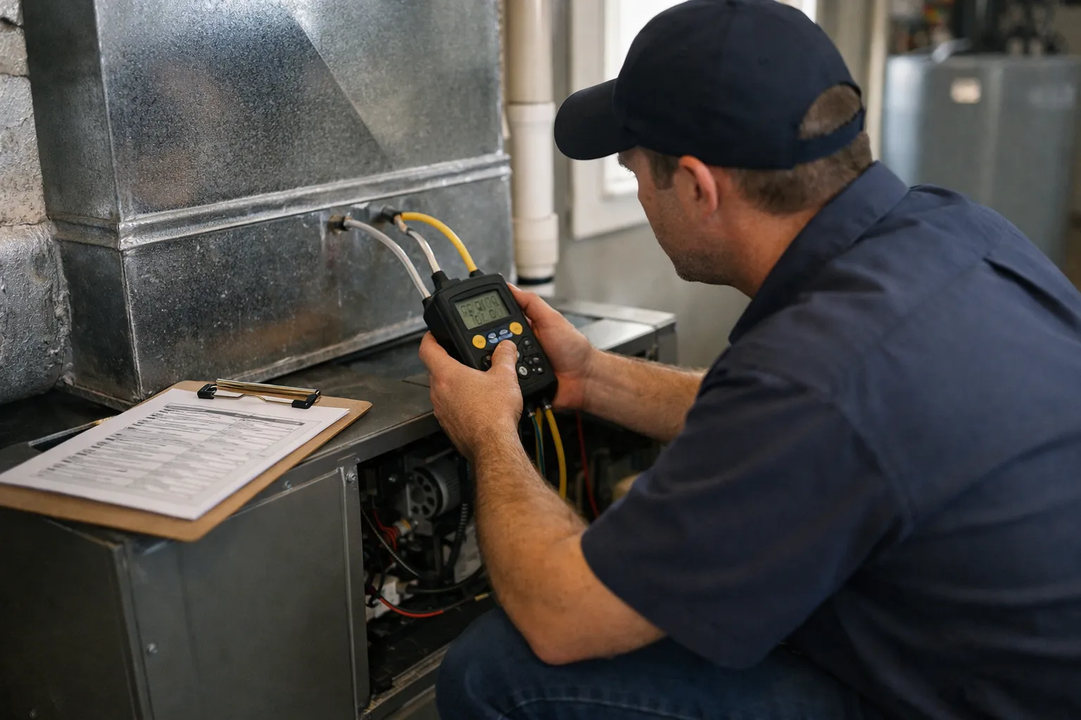
Introduction — What you'll learn and who this is for
Luxury in a home is often quiet and invisible: even temperature, measured humidity, and no surprise service calls. Achieving that stillness with modern heat pumps requires commissioning — a disciplined, documented verification that the installation performs as designed. This updated November 2026 guide is written for HVAC enthusiasts, technically literate homeowners, designers, and contractors who need a reliable, auditable outcome from a new heat pump purchase.
You'll find a concise, actionable checklist: what to prepare before the technician arrives; how to verify airflow, charge, and controls with today’s tools; what documentation to demand; and practical advice for low‑GWP refrigerants, cloud diagnostics, and winter verification. The guidance keeps pace with current 2026 practices — widespread adoption of communicating systems, stronger utility and incentive requirements for measured commissioning, and mature cloud portals with trend analysis and anomaly detection.
Prerequisites / Context — What commissioning means in November 2026
Commissioning in 2026 is a documented, measured verification that an installation meets design intent under representative conditions. It goes beyond start‑up or app pairing: it requires measured airflow, verified refrigerant charge per manufacturer procedure, deliberate control configuration, and accessible documentation for warranty, rebate, and resale purposes.
Key elements that have become standard by late 2026:
- Measured external static pressure (ESP) and documented delivered airflow (CFM) using accepted, auditable methods.
- Manufacturer‑approved refrigerant procedures specific to the refrigerant, expansion device (EEV/TEV), and inverter control logic.
- Control and thermostat configuration tailored to the home — correct wiring, proper sensor placement, sensible setback logic, and humidity strategy.
- Digital documentation: timestamped photos, diagnostic logs, and cloud‑stored commissioning records. QR tags linking equipment plates to commissioning PDFs are common.
Why the emphasis? Variable‑speed compressors, communicating controls, and the transition to low‑GWP refrigerants make charge, airflow, and control logic interdependent. In practice that means commissioning must be a measured sequence — airflow first, then refrigerant, then controls — recorded and archived.
Before commissioning day assemble these items for the technician:
- Exact model and serial numbers for outdoor and indoor units and any separate coil.
- Manufacturer installation and charging manuals (PDFs preferred) and the AHRI match reference used at selection.
- Basic house data: conditioned square footage, recent envelope upgrades, and any chronic comfort problems.
- Access to any utility or rebate requirements: many programs now require measured commissioning for incentive payment.
Expect the technician to arrive with calibrated instruments: micromanometer or wireless pressure transducers, a flow grid or TrueFlow plate or documented fan tables, temperature/humidity probes, and a digital refrigerant scale and manifold compatible with the refrigerant. Many technicians in 2026 also use Bluetooth manifolds and manufacturer cloud apps that time‑stamp and archive readings — request access credentials or an exported PDF.
Step 1: Confirm equipment match and installation basics
-
Verify model combinations and AHRI match
Why: unapproved coil/handler combinations or swapped blowers reduce capacity and efficiency. Action: ask the technician to display the AHRI match or manufacturer approval and photograph data plates (outdoor, indoor, coil). Save those photos in the house file.
-
Confirm line‑set practices and oil compatibility
Why: many low‑GWP agents have different oil chemistries and stricter cleanliness expectations. Action: confirm brazed joints are clean and leak‑free, check for required receivers/accumulators per the manual, ensure continuous suction line insulation, and document oil type compatibility where specified.
-
Inspect condensate management
Why: water damage is an avoidable failure mode. Action: identify trap location, secondary pan placement (attics and ceilings are high‑risk), float switches or alarms, and routing that prevents freezing or backflow during heavy storms.
-
Check electrical protections, grounding and firmware
Why: inverter drives are sensitive to voltage anomalies; firmware affects controls and diagnostic capability. Action: verify breaker sizing and disconnect, check for recommended surge protection, record firmware versions on service labels, and plan a firmware update if the installed software is not current.
Step 2: Commission airflow first — foundation of all other checks
Fundamental rule: you cannot reliably verify refrigerant charge or controls without verified airflow. Modern control algorithms respond to airflow and temperature; wrong airflow masquerades as charge or logic faults.
-
Measure external static pressure (ESP)
Why: ESP is the duct system’s resistance. Action: drill test ports and record total ESP across the air handler (supply minus return). Compare to the air handler’s published maximum; many modern residential designs target roughly 0.25–0.5 in. w.c. If measured ESP approaches or exceeds published limits, address duct improvements before final charge verification.
-
Document delivered airflow (CFM) by an accepted method
Why: register feel is not proof. Acceptable methods in 2026 include:
- ESP + manufacturer fan performance tables (document the table and tap location).
- Flow grid or TrueFlow plate at the air handler or filter slot.
- Register hood balancing for room‑by‑room verification when comfort is uneven.
Actionable target: many conventional designs still target roughly 350–450 CFM per ton; follow the manufacturer’s specified delivered CFM for each operating mode. Record method, numbers, and ambient conditions in the report.
-
Measure filter and grille pressure drops
Why: high‑MERV 1‑inch filters can significantly raise pressure drop. Action: if filter pressure drop is excessive, upgrade to a 4–5 inch media cabinet or enlarge the return grille to preserve airflow while retaining filtration efficiency.
-
Check return capacity and obvious duct leakage
Why: undersized returns or visible leaks cause imbalance and pressure swings. Action: note disconnected boots, leaky seams, or heavily restricted returns; consider targeted leakage repairs or a formal duct leakage test before concluding commissioning.
Step 3: Verify refrigerant charge using manufacturer‑approved procedures
With airflow verified, proceed to charge. By November 2026 many systems use EEVs, on‑board charging routines, or require charge‑by‑weight procedures; always follow the model‑specific manual.
-
Confirm the model’s charging procedure in the manual
Why: variable‑speed inverter systems behave differently than single‑stage units. Action: the technician should consult the manual on site. Some models use subcooling targets; others include an automatic on‑board charge routine that must be invoked from the service menu.
-
Record stabilised indoor and outdoor conditions
Why: charge targets depend on conditions. Action: log outdoor dry bulb, return dry bulb and wet bulb (or relative humidity), and stabilized head pressures and temperatures before and after adjustment.
-
Use calibrated instrumentation and archive the event
Why: “it’s in the green” is not auditable. Action: insist on a written log or time‑stamped photos of manifold readings, net refrigerant added (by weight), and any service menu screenshots showing on‑board diagnostic results. If the installer uses a manufacturer cloud portal, request PDF export or shared access.
-
Track refrigerant inventory and provide a tag
Why: traceability supports regulation compliance and future service. Action: request a commissioning tag or certificate listing refrigerant type, amount charged, and serial numbers. Many installers now issue a QR tag that links to the full commissioning report.
Step 4: Validate heating performance, defrost behavior, and low‑ambient operation
Cooling verification alone is insufficient. Heat pump behavior in low ambient and during defrost defines winter comfort and efficiency.
-
Demonstrate inverter ramping and staging
Why: variable‑speed systems deliver comfort through long, low outputs rather than frequent cycling. Action: ask the technician to demonstrate low and high outputs, measure supply air temperature delta and runtime at each output, and document ramp times and setpoints.
-
Confirm auxiliary heat logic and lockouts
Why: default control logic can allow unnecessary auxiliary heat. Action: verify setback behavior, outdoor lockouts for auxiliary heat, and the temperatures at which backup heat engages; record these settings in the report.
-
Inspect defrost sensors and outdoor drainage
Why: demand‑defrost strategies depend on correct sensor placement and clear drainage. Action: confirm sensor wiring and placement per the manual, and ensure outdoor condensate and meltwater clear paths. If the home is in a cold region, schedule a cold‑weather follow‑up or remote monitoring to confirm real‑world defrost frequency.
Step 5: Commission controls, sensors, and thermostat strategy
Controls turn equipment capability into lived comfort. Commissioning ensures the system’s intelligence aligns with occupant expectations.
-
Verify thermostat type, wiring, and software settings
Why: incorrect mode or wiring undermines performance. Action: confirm correct control type (communicating vs conventional), verify wiring, and record thermostat firmware and calibration offsets.
-
Set fan behavior and humidity strategies intentionally
Why: fan mode and dehumidification strategies influence comfort and condensate management. Action: choose fan strategy consistent with climate goals; in humid climates avoid continuous fan speeds that re‑evaporate condensate. Program dehumidify‑overcool or blower modulation settings as appropriate.
-
Plan setback and zoning to avoid auxiliary heat use
Why: aggressive setbacks can trigger costly backup heat. Action: prefer conservative setbacks, staged schedules, or multi‑zone control. Document the setpoint strategy and rationale in the commissioning report.
-
Confirm sensor placement and cross‑check readings
Why: thermostat misplacement misleads the system. Action: compare thermostat readings with an independent calibrated thermometer/hygrometer and note offsets in the report. If remote sensors are used, verify their connectivity and placement.
Step 6: Demand usable documentation and ongoing verification
Commissioning without an accessible record is incomplete. Insist on a commissioning report you can reference — digital preferred.
The report should include at minimum:
- Model and serial numbers for all equipment and coil identifiers.
- Measured ESP, method used, and estimated delivered airflow (CFM) with ambient conditions.
- Filter type/size and measured filter pressure drop.
- Charging method used, measured subcooling/superheat (with conditions), and net refrigerant added.
- Cooling and heating temperature splits, indoor humidity at time of test, and basic heating verification readings.
- Thermostat/control settings: staging, auxiliary lockouts, fan mode, and any dehumidify settings.
- Photos of line‑set routing, brazed joints, electrical connections, condensate routing, and installed sensors.
- Firmware versions updated and cloud portal access details or exported logs.
Why digital? Manufacturer and third‑party commissioning apps increasingly provide time‑stamped logs, runtime histograms, and automated anomaly detection. Request exported PDFs or shared folder access and retain these files for warranty, utility rebate compliance, and resale.
Common mistakes that keep new heat pumps from performing
- Charging before verifying airflow. Incorrect airflow makes a correct charge meaningless.
- Ignoring static pressure. High ESP reduces capacity, increases noise, and stresses blowers.
- Accepting default thermostat firmware and generic settings. Outdated firmware and defaults can negate inverter advantages.
- No refrigerant traceability. Without a tag or log, future service on low‑GWP systems is more costly and warranty issues become harder to resolve.
- No follow‑up during representative seasons. An initial warm‑season commissioning may not expose winter defrost or low‑ambient quirks — schedule a cold‑weather follow up or remote diagnostic review.
Pro tips for enthusiasts who want exceptional results
- Require commissioning in the contract. Specify measured airflow, ESP, and charge logs as deliverables. If the installer will not provide those, consider a different contractor or an independent commissioning specialist.
- Ask for room‑by‑room balancing when comfort is uneven. Register and zone balancing can markedly improve perceived comfort without changing equipment.
- Plan filter cabinet size early if you want high‑MERV filtration. A 4–5 inch media filter preserves airflow better than a restrictive 1‑inch at the same MERV level.
- Schedule a 30–90 day remote or on‑site follow‑up. With cloud diagnostics, a remote review of runtime, staging trends, and defrost frequency three months after commissioning often catches issues a single visit misses.
- Retain photos, QR tags and exported logs with the home file. They materially speed future diagnostics and support resale disclosure.
FAQ
Is commissioning worth paying extra for on a new heat pump?
Yes. Proper commissioning reduces callbacks, secures efficiency and comfort, and produces auditable records for warranty and incentive compliance. Commissioning is commonly a small fraction of installation cost but typically delivers measurable savings in comfort and reduced service calls over the equipment life.
What specific numbers should I insist the contractor record?
At minimum: total external static pressure and the method used to derive airflow (with delivered CFM); final refrigerant verification per the manufacturer (subcooling or superheat); net refrigerant added (by weight); thermostat/control settings (staging, aux lockouts, fan mode); and ambient conditions recorded at each measurement.
How do low‑GWP refrigerants change commissioning procedures?
Low‑GWP agents frequently require tighter charge tolerances, different oils, and stricter brazing/leak standards. Many manufacturers specify charge‑by‑weight compensation and on‑board charging routines. Follow the exact model manual and insist on an auditable charge log and refrigerant tag.
Can commissioning be done remotely or require cloud tools?
Initial physical measurements (ESP, CFM, line pressures) require onsite work. However, cloud portals and manufacturer apps enable remote follow‑up: trend analysis, firmware pushes, and anomaly detection. Insist on exported logs or provider access so you can review performance after the visit.
What's the fastest red flag that commissioning wasn't properly done?
No measured static pressure or airflow documentation in the handover packet. If the only evidence is “it runs,” critical performance variables were likely not verified — request the full commissioning report before accepting final payment.
Sources and guidance: manufacturer installation and charging manuals; AHRI match directories for equipment pairing; ACCA Manuals D and S for duct and equipment benchmarks; and local authority and EPA guidance for refrigerant handling and reporting. For incentive requirements, consult your local utility or program documentation for commissioning evidence rules.