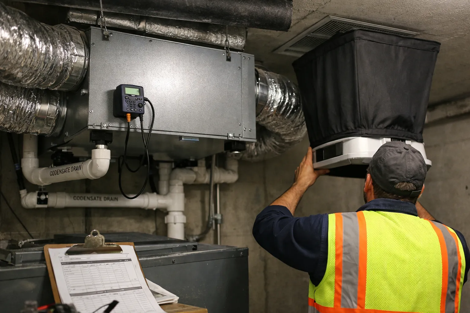
Heat‑recovery ventilators (HRVs) and energy‑recovery ventilators (ERVs) are now a common solution in multifamily retrofits that aim to meet increasingly strict ventilation and energy targets established by codes and lenders in 2024–2026. This guide walks installers, commissioning agents and HVAC enthusiasts through a practical, step‑by‑step process for assessing, specifying, installing and commissioning HRV/ERV systems in multifamily retrofits with special attention to moisture control, controls integration and flow balancing.
Why HRV/ERV in Multifamily Retrofits?
Multifamily retrofits typically tighten the building envelope, increasing the need for controlled mechanical ventilation. HRVs and ERVs recover sensible (HRV) and sensible plus latent (ERV) energy from exhaust air to reduce heating/cooling loads while providing continuous ventilation. Choosing and commissioning the right system preserves indoor air quality (IAQ) without excessive energy penalties and minimizes moisture issues that commonly appear in retrofit scenarios.
When to choose HRV vs. ERV
- Cold, dry climates: HRVs are often preferable because latent transfer is less important and ERVs may pass moisture into conditioned space.
- Mixed and hot‑humid climates: ERVs are typically better because they limit moisture transfer into living spaces during humid months.
- Projects with balanced heating/cooling loads and continuous ventilation intent: ERVs provide year‑round latent management; HRVs give slightly higher sensible recovery efficiency.
Pre‑Installation assessment (what to measure first)
Before specifying equipment, gather these data on each affected dwelling unit or common area:
- Unit floor area and bedroom count (to calculate ASHRAE 62.2 ventilation rates).
- Existing duct routing, grilles/terminations and available mechanical rooms.
- Envelope tightness (blower door results if available) and potential inter‑zone leakage paths.
- Baseline indoor humidity and temperature patterns (1–2 weeks of spot RH/T logging is ideal).
- Available roof/soffit penetrations for intake/exhaust placement and code‑required clearances.
Use the ASHRAE 62.2 formula for single‑family dwelling units as the starting point in many jurisdictions: Qfan = 0.03 × floor area (ft²) + 7.5 × (number of bedrooms + 1) (cfm). For a 1,000 ft² two‑bedroom unit, that results in ~53 cfm continuous ventilation. Verify local code — some jurisdictions set minimums or require centralized systems for corridors and common spaces.
Unit selection and sizing
Select units to match per‑unit or common‑system ventilation requirements with these criteria:
- Rated airflow: Unit airflow at rated external static pressure should meet or slightly exceed design continuous ventilation flow for the number of units it serves.
- Recovery efficiency: Look for sensible recovery efficiency (HRV) or total enthalpy efficiency (ERV) at realistic operating flows; AHRI data and manufacturer performance curves are essential.
- Fan power and controls: ECM fans with variable speed allow precise balancing and reduced energy use. Verify minimum and maximum speeds and fan curves.
- Frost control: For cold climates, specify units with proven defrost strategy (pre‑heat, exhaust recirculation or bypass) and confirm manufacturer performance at −10 °F to 14 °F if applicable.
- Filter capacity: Units should accept at least MERV 6–8 filters; if MERV 13 is needed for IAQ, verify fan capacity to overcome pressure drop or plan for larger units.
Practical ductwork and termination practices
Good duct design reduces pressure imbalances, noise and maintenance headaches:
- Minimize elbows and long runs in unit supply/exhaust trunks. Use smooth, semi‑rigid or metal ducting where possible.
- Provide straight runs and plenum space for flow measurements near the unit. Avoid placing balancing dampers where access will be obstructed.
- Intake and exhaust terminations must be separated per code and manufacturer guidance, and located to avoid contamination (rooftop or sidewall clearances, bird/rodent screens).
- Install dedicated grilles in kitchens and bathrooms sized for low face velocity (reduces noise). Use adjustable diffusers where fine tuning is required.
- In multi‑unit systems, avoid sharing ventilation air between units. Each dwelling should have a balanced supply/exhaust or system designed to prevent cross‑contamination.
Controls strategy and integration
Controls are central to performance and occupant comfort. For multifamily retrofits, focus on these control elements:
- Continuous baseline flow: Set fans to run continuously at the design “continuous” flow rate. Use ECM speed presets to achieve flows without excessive noise or energy.
- Boost functions: Include humidity sensors (RH) in bathrooms and kitchens with boost setpoints (e.g., engage at 55–60% RH) and timer‑off logic. Occupancy sensors are acceptable supplements for kitchen boost.
- Interlocks and safety: Ensure boost does not create excessive depressurization that risks backdrafting of combustion appliances; test exhaust pressure effects on adjacent units and common spaces.
- Remote monitoring: For large retrofits, consider a gateway that reports filter pressure drop, total fan runtime, faults and average flow to facilities or property managers for proactive maintenance.
- CO2 sensors: For large common spaces (gyms, community rooms) add CO2 monitoring to trigger increased ventilation during occupancy peaks; for individual units continuous RH control is often sufficient.
Step‑by‑step commissioning and balancing procedure
Commissioning should be a documented sequence. Below is a practical acceptance test protocol for each unit or system.
-
Pre‑startup checklist
- Verify correct power, control wiring and fan direction.
- Confirm filters, access panels and condensate drains are installed and accessible.
- Record static pressure available at unit in. w.g. (external static pressure) and compare to fan curve.
-
Baseline airflow calibration
- Using a calibrated flow hood or capture hood at supply and exhaust grilles, measure airflow. For multi‑branch systems, use pitot traverse in trunks or manufacturer suggested measurement points.
- Adjust fan speed and local balancing dampers to achieve design continuous flows within ±10% of design.
- Record supply, exhaust and net flow. For balanced systems target net flow ≈0 cfm; project intent may call for slight positive or negative pressure—document target and verify pressure delta with an electronic manometer (typical target ±1–3 Pa between unit and corridor).
-
Frost/defrost verification (cold climates)
- Trigger defrost mode (via low outside temperature simulation or manufacturer procedure) and verify transition, preheat activation and recovery within manufacturer‑specified timeframes.
- Measure supply temperature recovery after defrost to confirm occupant comfort and energy impacts.
-
Controls functional test
- Test continuous mode, boost triggers (RH setpoints, manual boost switches) and timer behavior.
- Verify alarms and remote reporting (if installed) for filter change, fan failure and high differential pressure.
-
Moisture response test
- Simulate humidity generation (e.g., running shower for a short period in bathrooms) and confirm boost engages and RH drops toward baseline within expected time (document target e.g., 60% RH within 20–30 minutes).
- Confirm ERV sensible/latent behavior: compare enthalpy or RH of supply air entering unit vs. outdoor air if you have instrumentation; ERVs should reduce latent load entering the space in humid months.
-
Noise and vibration
- Measure sound at living room and bedroom grilles per project specification. Typical acceptance targets are 30–40 dB(A) at seated positions for continuous ventilation; verify with tenant expectations and local standards.
-
Documentation and occupant instructions
- Provide each unit occupant or property manager with operating instructions, filter change intervals, typical noise expectations and a simple troubleshooting guide.
- Deliver commissioning report recording measured flows, pressures, control setpoints and photos of installation and damper positions.
Addressing moisture and condensation risks
Moisture issues are the most frequent failure mode in retrofits that add ventilation. Follow these practices:
- In humid climates, choose ERVs with enthalpy wheels or membrane cores that reduce latent transfer into conditioned space.
- Avoid routing intake air through crawlspaces or damp plenums; outdoor intakes must be above grade and away from drainage flow.
- Ensure condensate drains have traps and slope; check for icing risk in heat exchangers during winter and verify defrost prevents condensate freeze‑up.
- Set bathroom boost to a conservative RH (55–60%) so short activities trigger removal but avoid constant cycling.
Maintenance and handover
Handover and maintenance define long‑term success:
- Filter replacement: typically every 3–6 months; use pressure drop monitoring for densely occupied buildings.
- Inspect core/heat exchanger and condensate drain annually; replace cores per manufacturer (commonly 5–10 years depending on pollutant load).
- Verify fan curves and motor amp draw yearly to detect bearing wear or blocked filters.
- Provide a simple tenant sheet: continuous ventilation purpose, boost operation, how to change filters, and contact for repairs.
Sample quick calculation (typical 12‑unit retrofit)
Hypothetical: twelve 1,000 ft² two‑bedroom units. Per ASHRAE 62.2 (single‑unit approach), each unit needs ~53 cfm continuous. Total system capacity = 12 × 53 = 636 cfm. Using twelve separate ERVs sized ~60 cfm each keeps duct runs short and allows unit autonomy; alternatively, a set of centralized units with dedicated supply/exhaust distribution can be used, but must ensure individual unit isolation to prevent cross‑contamination.
Common pitfalls and how to avoid them
- Under‑sized fans or ignoring ESP: Check external static pressure in design and select fans with margin for filters and grilles.
- Improper damper access: Balance dampers placed behind cabinets are never adjusted. Provide access panels.
- Cross‑contamination: Shared return/supply between units without proper backflow prevention causes odors and IAQ issues—design for sealed unit flows.
- No commissioning data: Without recorded test numbers, future troubleshooting becomes slow and costly—document everything.
Final checklist for acceptance
- Measured supply and exhaust within ±10% of design.
- Net unit pressure within project target (typically ±1–3 Pa relative to corridor).
- Filters installed and documented filter type and replacement interval.
- Defrost strategy validated (cold climate projects).
- Controls: continuous speed, boost functions, alarms and remote reporting tested.
- Commissioning report delivered to owner/operator with photos, graphs and setpoints.
HRV/ERV retrofits in multifamily buildings deliver occupant health and energy benefits, but they demand careful design, attention to moisture dynamics and thorough commissioning. Follow the step‑by‑step process above, use the right tools (flow hood, manometer, temperature/RH probes), and document outcomes. Proper commissioning and maintenance turn investment into durable performance.