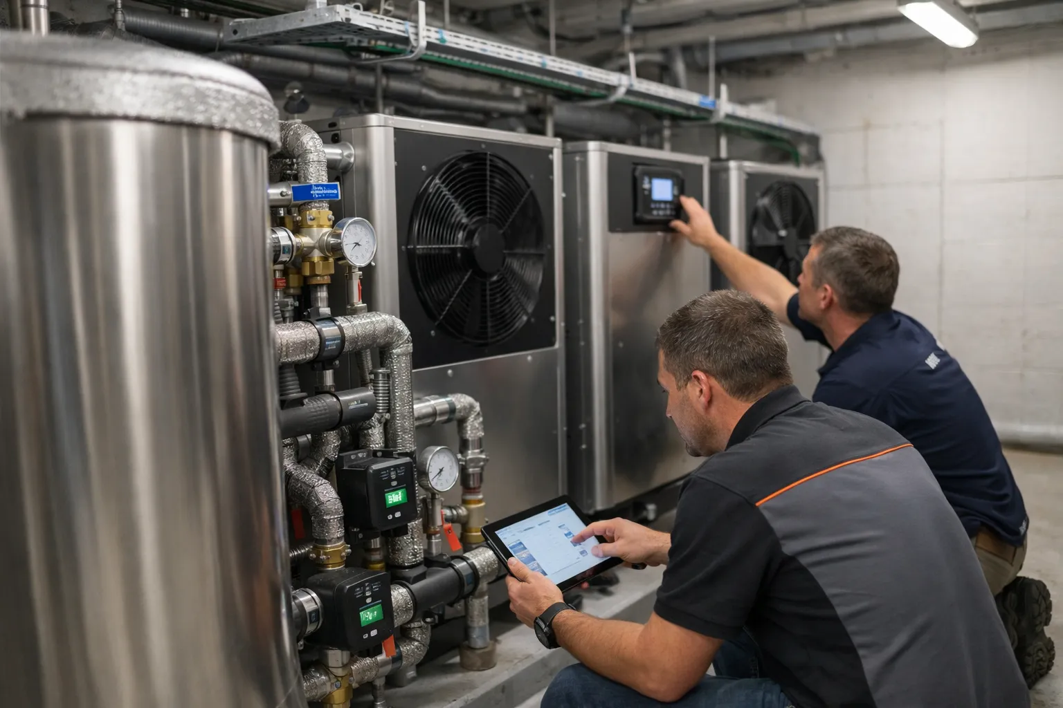
Electrified hydronic heating using cascaded heat pumps remains one of the most practical pathways to decarbonize buildings while preserving existing low‑temperature radiant infrastructure. This updated October 2026 guide keeps the original hands‑on approach but adds recent field lessons, technology shifts and policy context that matter today: broader adoption of A2L/HFO refrigerants, widespread inverter‑driven modular units, tighter grid integration expectations, and more rigorous performance verification practices. This is written for HVAC practitioners, consulting engineers and technically literate building owners planning radiant retrofits with cascaded air‑to‑water (A2W) or water‑to‑water heat pumps.
Prerequisites and context: what changed since 2024–2025
- Market and technology: By 2026, inverter‑driven multi‑module heat pumps with electronic expansion valves and advanced part‑load maps are standard for commercial cascades. These reduce cycling and improve low‑temperature COP compared with older fixed‑speed units.
- Refrigerants and codes: Lower‑GWP HFO blends and A2L refrigerants (mildly flammable) became the mainstream choice for many manufacturers. Local adoption of A2L code adjustments varies—check your jurisdiction for installation limits, room size rules, ventilation and leak‑detection requirements before specifying equipment.
- Grid and incentives: Utility demand‑response programs and time‑of‑use rates are now important design inputs. Many rebate programs and tax incentives through 2026 prioritize high‑efficiency heat pumps and verified performance—plan metering and data logging accordingly.
- Performance verification: Owners increasingly expect baseline and post‑installation metrics (seasonal performance factor (SPF), logged COP, run‑time histograms). Commissioning now commonly includes a 30–90 day monitored verification period to qualify for rebates or energy performance contracts.
Step 1 — Initial assessment: what to survey before design
- Room‑by‑room heat loss and delivery temp needs: Measure or recalculate heat losses at the target supply temperature for the existing radiant system. Modern runs with thin screed or panels often work at 30–35 °C; older concrete slabs and legacy radiators may require 40–45 °C. Retain conservative margins if insulation upgrades are not planned.
- Distribution hydraulics and loop condition: Inspect piping diameter, balancing valves, manifolds, air vents, and water quality. Flush radiant loops fully; run a water analysis (pH, conductivity, dissolved oxygen) and add corrosion inhibitors where appropriate.
- Existing plant interactions: Catalogue boilers, controllers, and backup systems. Decide whether boilers will be retained as emergency backup, mixed with a plate heat exchanger for DHW, or decommissioned.
- Space & ventilation constraints: A2W units require refrigerant piping clearances and safe service access. For A2L refrigerants, ensure dedicated mechanical room ventilation and leak detection per local rules.
- Utility signals and incentives: Identify demand‑response, time‑of‑use, and rebate requirements. Many programs require interval metering, data retention, or third‑party commissioning reports.
Step 2 — Choosing equipment and cascade topology
Topology choices remain similar, but component expectations have evolved:
- Parallel staged A2W modules (modern default): Multiple identical inverter‑driven A2W units piped in parallel to a hydraulic separator/buffer tank. Advantages today: precise modulation, soft‑start staging, and built‑in cloud telemetry on many commercial units.
- Primary‑secondary with plate exchangers: Useful to separate potable DHW and for applications that require different pressure regimes or freeze protection. Plate heat exchangers are often combined with a glycol source loop in cold climates.
- Water‑to‑water or brine loops: Still appropriate for lake, ground or district heat sources; these systems increasingly use variable‑speed compressors sized for lower leaving‑water temperatures to maximize COP.
Essential components now typically include:
- Buffered storage sized to prevent short cycling and to enable grid‑interactive strategies
- Variable‑speed circulators (ECM) with pressure/flow control and VFDs
- Hydraulic low‑loss header or plate separator
- Electronic mixing/tempering valves and actuators for DHW
- Distributed sensors: entering/leaving water, supply setpoint, outdoor air, refrigerant pressure transducers and leak detectors
- Control platform with BACnet/IP or Modbus TCP and secure cloud telemetry for analytics
Step 3 — Sizing: heat pumps, buffer volume and pumps (updated best practices)
Heat pump capacity still comes from the building design load at the selected supply temperature. Newer manufacturer performance maps provide extended part‑load efficiency figures; use these when modeling expected seasonal performance.
Buffer sizing — unchanged formula, updated practice
Buffer prevents short cycling. Use the same energy‑based formula:
V (L) = (Q (kW) × t_min (s)) / (cp (kJ/kg·K) × ΔT (K))
Where cp ≈ 4.18 kJ/kg·K. Maintain a minimum run time of 5–10 minutes for inverter units; many manufacturers now recommend the lower bound (5 minutes) because soft‑start modulation reduces the mechanical stress of starts. Still, plan buffer sizing for realistic ΔT and staging—250–500 L per ~20 kW remains a useful rule of thumb, but verify with manufacturer minimum run times and plant control strategy.
Pump selection and flow strategies
Use variable flow primary and secondary loops. Design flow using:
Flow (m³/h) = Q (kW) / (ρ × cp × ΔT)
Where ΔT is supply‑return. Contemporary radiant projects commonly operate with ΔT = 4–6 K (lower than older 5–8 K advice) enabled by electronic balancing and variable‑flow control. Lower ΔT reduces supply temperature needs but increases distribution pumping energy—run a simple pump power trade‑off calculation and model annual pumping energy.
Step 4 — Hydraulic schematic and field layout (practical tips)
- Place the buffer tank between heat pumps and the distribution header; use a low‑loss header sized for the combined pump flows.
- Install robust filtration (dirt separators, Y‑strainers) and auto air vents; add magnetic filters where ferrous corrosion is a concern.
- Each heat pump requires a check valve and isolation ball valves for service. Include bypass lines for maintenance and winterization.
- Locate sensors where they read true system conditions: on the buffer supply and return and on the distribution header. Avoid tap placement downstream of strainers or circulators that bias readings.
Step 5 — Controls: sequencing, weather compensation, grid interaction and failover
Control design is now a critical performance lever. New expectations in 2026 include grid‑aware operations and cloud analytics in addition to traditional cascade logic.
- Cascade sequencing: Stage by capacity and runtime; prefer modulation and soft lead/lag rotation to equalize wear. Use minimum run timers and soft‑start algorithms embedded in modern inverters.
- Weather compensation: Use outdoor‑reset curves but flatten curves to protect COP. Pair weather compensation with indoor setback where occupancy or thermal mass allows.
- Grid‑aware setpoints: Integrate demand‑response signals and time‑of‑use pricing. Use the buffer tank as a short‑term thermal battery to pre‑charge during low‑cost periods and shed load during peaks.
- Defrost coordination: Coordinate defrost across modules so no more than one unit defrosts at once, preserving plant capacity. Modern controllers support coordinated defrost schedules and staggered timers.
- Communications and cybersecurity: Use BACnet/IP or Modbus TCP and secure cloud telemetry. Implement passworded devices, network segmentation for building controls and logging for audit and performance verification.
Step 6 — Commissioning checklist: updated and extended
- Pre‑start: verify mechanical clearances, refrigerant piping routing and ventilation per local A2L rules, and electrical installation against manufacturer drawings.
- Hydraulic leak test and flush: pressure test and flush to remove particulates; treat water for corrosion control and add glycol only where freeze protection is required—avoid unnecessary glycols that lower heat‑transfer efficiency.
- Refrigerant work: A2L/HFO charges and leak checks must be performed by certified technicians and in accordance with local code. Install electronic refrigerant leak detectors where required.
- Verify pump flows and ΔT at several load points; validate VFD behavior and pressure control across zones.
- Run cascade through staging sequences, confirm minimum run times, lead/lag rotation and coordinated defrost behavior.
- Control tests: confirm outdoor‑reset operation, DR signal handling, DHW priority and BMS integration. Validate alarm notification pathways and remote access for firmware updates.
- Performance baseline: log COP, supply/return temps, runtime histograms and electrical consumption for 30–90 days. Produce a measured performance report to support rebate or financing requirements.
Common pitfalls in 2026 and how to avoid them
- Ignoring grid signals: Without integrating demand‑response/time‑of‑use strategies you miss operating‑cost savings. Add simple buffer control modes that enable pre‑charging.
- Poor refrigerant risk planning: A2L adoption is widespread but not universal—ensure mechanical room ventilation and leak detection are designed to code and that service staff are trained.
- Insufficient data logging: Many rebate and performance contracts now require interval data. Install meters and loggers during commissioning.
- Underestimating pumping energy: Lower ΔT radiant designs can raise circulation energy. Model pump energy over the heating season and size ECM pumps accordingly.
- Neglecting water treatment: Corrosion and microbiological growth remain leading causes of degraded heat transfer—commission a water management plan and schedule for monitoring.
Pro tips — advanced recommendations
- Use predictive control where possible: pair weather forecasts and utility price signals with thermal mass models to optimize when to run modules.
- Consider hybrid strategies: for buildings with very high peak loads, a small gas boiler or electric resistance heater configured as emergency backup and integrated into the control logic reduces capital cost while keeping operational emissions low when grid intensity is low.
- Specify built‑in analytics and local data retention: cloud dashboards are useful, but local data buffering ensures continuity through connectivity outages and meets many rebate program requirements.
- For DHW: prefer plate‑exchanger decoupling and prioritize DHW charging to the buffer during off‑peak hours. Consider a dedicated higher‑temperature loop for safety and legionella control.
Updated example: mid‑rise retrofit with grid‑aware cascade (contextual numbers)
Scenario: 2026 retrofit of a 48‑unit mid‑rise in a northern U.S. climate. Existing slab radiant system with design load approximately 140 kW at 40 °C. Proposed plant:
- Three inverter‑driven A2W modules rated ~50 kW each (modules sized so two meet typical load, third covers peaks and defrost).
- 1,200 L buffer tank for minimum run time and to enable 1–2 hours of pre‑charge during low‑cost electricity periods.
- Low‑loss header, VFD primary pump and secondary zonal pumps with pressure independent control valves (PICVs).
- Control system integrated with utility demand‑response and metered for rebate documentation; cloud telemetry for remote FDD (fault detection and diagnostics).
Designers modeled season‑long pump energy and determined ΔT = 5 K gave the best balance of distribution and plant efficiency. Commissioning included a 60‑day monitored verification for incentive qualification and tune‑up of outdoor reset curve to preserve COP during cold snaps.
Maintenance and long‑term monitoring (2026 emphasis)
- Monthly: visual checks, pump current, leak detector status, buffer insulation integrity and basic log checks.
- Quarterly: clean strainers, verify air separators, check water treatment chemistry and recalibrate mixing valves.
- Annually: refrigerant leak inspection by certified technician, inverter diagnostics, firmware updates and seasonal COP analysis using logged data.
- Ongoing analytics: implement alerts for low ΔT, repeated short cycles, abnormal refrigerant pressures and falling seasonal COP so maintenance can be proactive.
FAQ
Do I have to use A2L refrigerants for cascades in 2026?
No. A2L and lower‑GWP HFO blends are common because manufacturers favor them for performance and GWP benefits, but non‑A2L options still exist. Your choice should be driven by local code, mechanical‑room constraints, service capability and the manufacturer's packaged‑unit options.
How big should the buffer tank be for a multi‑module cascade?
Use the energy‑based formula in this guide. As a quick reference, designers often specify 250–500 L per ~20 kW of heat‑pump capacity depending on ΔT and minimum run time. Confirm with the manufacturer's minimum‑run and control recommendations.
What are the most important commissioning data points for rebate programs?
Common requirements include interval electrical consumption, supply and return temperatures, runtime per module, and a verified seasonal performance metric (COP or SPF). Check program rules early so you install the required meters and logging systems before start‑up.
Can cascaded heat pumps handle DHW spikes?
Yes—if you design buffer capacity and DHW priority into controls. Plate heat exchangers for potable separation and a dedicated DHW charging strategy (pre‑heat during off‑peak) are common approaches. For large spikes, a brief electric backup heater may be configured as emergency support.
How should I plan for operations and maintenance staff training?
Require refrigerant‑handling certification for A2L/HFO service, train staff on inverter diagnostics and cloud telemetry, and include a documented O&M manual with control sequence explanations and alarm response procedures. Annual refresher training reduces operational risk.
Final recommendations
Cascaded hydronic heat‑pump systems remain a robust retrofit solution for low‑temperature radiant systems in 2026. The highest‑impact changes since 2024 are widespread inverter modulation, broader A2L/HFO adoption with associated code considerations, and increasing expectations for grid‑integration and verified performance. Success depends on careful pre‑assessment, correct hydraulic design (buffering and decoupling), deliberate control sequences that include grid awareness, thorough commissioning with 30–90 day monitoring, and active long‑term analytics. For large projects, start with a pilot sub‑block to validate controls and metering before full rollout.
Useful resources: manufacturer installation manuals, local building department guidance on A2L/HFO refrigerants, utility program technical requirements, and ASHRAE/industry commissioning guidance for heat‑pump systems.