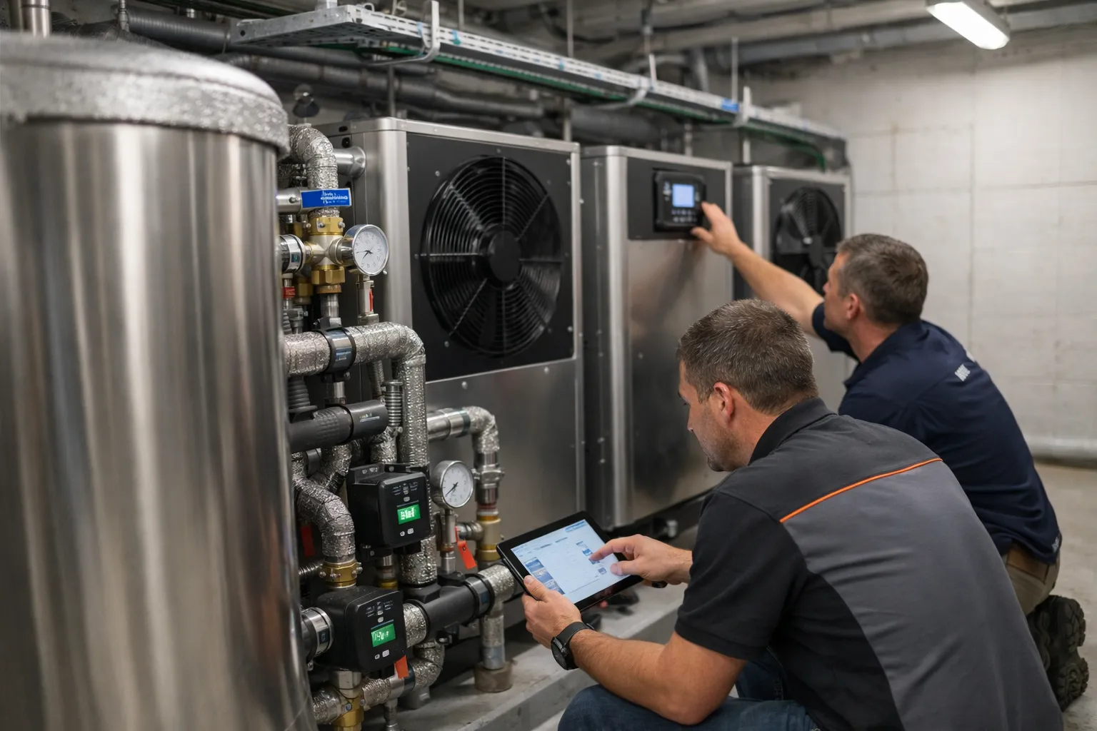
Electrified hydronic heating using cascaded heat pumps is a proven pathway to decarbonize buildings while using existing low‑temperature radiant infrastructure. This hands‑on guide walks HVAC enthusiasts through planning, sizing, piping, control strategy, commissioning and common pitfalls when retrofitting low‑temperature radiant floors or panels with cascaded air‑to‑water (A2W) or water‑to‑water heat pump arrays.
Why a cascade for low‑temp radiant retrofits?
Low‑temperature radiant systems (supply 30–45 °C) pair well with heat pumps because they operate at favorable coefficients of performance (COP). A cascade — two or more heat pumps staged together with hydraulic decoupling and buffer storage — delivers modular capacity, redundancy, improved part‑load efficiency and controlled defrost/staging behaviour. Cascades also let you match building load variability (zonal radiant control, DHW spikes) without oversizing a single large unit.
Initial assessment: what to survey before design
- Thermal load and distribution: Perform a room‑by‑room heat loss and determine the delivery temperature required by the radiant system. Low‑mass floor slabs and panel systems typically need 30–40 °C; older concrete slabs may need 40–45 °C.
- Existing plant interactions: Identify boilers, existing pumps, manifolds, mixing valves and controls. Decide if boilers remain as backup or can be decommissioned.
- Hydronic condition: Check piping sizes, insulation, air vents, strainers and water quality; radiant loops must be flushed and, often, treated to prevent corrosion.
- Space & mechanical room constraints: Cascade units require clearances for service, condensate and refrigerant piping (or hydraulic connections for water‑loop units).
- Code & refrigerant considerations: Verify local codes for equipment using A2L refrigerants (e.g., R‑454B) and ensure installers are certified for refrigerant handling. Check incentives and rebate eligibility (many 2024–2026 programs favor heat‑pump retrofits).
Choosing equipment: cascade topology and essential components
Common cascade topologies:
- Parallel staged A2W heat pumps: Multiple identical air‑to‑water units piped in parallel to a common hydraulic decoupling and buffer tank. Best for rooftop or mechanical room installs.
- Primary‑secondary with plate heat exchangers: Useful when decoupling refrigerant/water loops or separating potable DHW from source loops.
- Water‑to‑water compressors (brine loops): For district loops or where ambient heat sources (e.g., lake, groundwater) are available.
Essential components:
- Buffered storage tank sized to prevent short cycling
- Primary and secondary circulators with variable speed drives
- Low‑loss header or hydraulic separator
- Plate heat exchanger(s) for system decoupling (optional)
- Mixing/tempering valves for DHW or high‑temperature zones
- Sensors: entering/leaving water temps, supply temp, outdoor air sensor, pressure transducers
- Control hardware supporting cascade sequencing and communications (Modbus/BACnet)
Sizing: heat pumps, buffer volume and pump selection
Heat pump capacity is selected from building design load at the target supply temperature. For low‑temp radiant, take design at 35–45 °C supply depending on system. Use manufacturer performance maps — COP can drop significantly with higher supply temps and colder outdoor air.
Buffer sizing — simple calculation
A buffer tank prevents short‑cycling. Use this formula:
V (L) = (Q (kW) × t_min (s)) / (cp (kJ/kg·K) × ΔT (K))
Where cp for water ≈ 4.18 kJ/kg·K and density ≈ 1 kg/L. Example: 20 kW unit, minimum run time 300 s (5 min), allowable ΔT = 5 K:
V = (20 × 300) / (4.18 × 5) ≈ 287 L
Rule‑of‑thumb: minimum run time 5–10 minutes; aim for 250–500 L per 20 kW of heat‑pump capacity depending on ΔT and staging strategy.
Pump selection
Select pumps to deliver design flow at the planned ΔT. System flow (m³/h) = Q (kW) / (ρ × cp × ΔT) where ΔT is supply‑return temperature difference. Use VFD pumps and pressure sensors to maintain differential pressure across manifold loops and enable variable flow to rooms/zones.
Hydraulic schematic and field layout (practical tips)
- Place the buffer tank centrally between heat pumps and distribution header. Use a low‑loss header or hydraulic separator to decouple pump curves.
- Install strainer and dirt‑separator on the return side before pumps and plate exchangers; include air separators and automatic vents on high points.
- Use check valves on each heat‑pump supply to prevent backflow and ensure correct staged operation.
- Provide isolation valves and bypasses for service and winterization.
- Keep sensor tap locations repeatable and upstream/downstream of strainer or pumps to avoid biased readings.
Controls: sequencing, weather compensation, and failover
Design control sequences before equipment arrives. Key sequences:
- Cascade staging: Stage units by capacity or runtime to maintain supply temperature; use minimum on/off timers and soft start to avoid compressor damage.
- Weather compensation: Implement outdoor‑reset curves so supply setpoint tracks outdoor temperature; for low‑temp radiant, flatten the curve to limit supply temp increases that harm COP.
- Lead‑lag rotation: Rotate lead unit periodically to equalize wear across compressors.
- Defrost coordination: For air‑source units, coordinate defrost so only one unit defrosts at a time to preserve plant capacity.
- Boiler backup and DHW priority: When integrating legacy boilers, implement lockout and enable stages only when heat pumps cannot meet supply or DHW demands; consider plate exchanger decoupling for DHW to maintain potable separation.
Communications: prefer BACnet/IP or Modbus TCP to integrate into building automation. Archive key variables (unit status, COP estimate, energy meters, alarms) for O&M and performance verification.
Commissioning checklist: step‑by‑step
- Pre‑start: verify mechanical clearances, mountings, piping supports, and electrical connections per manufacturer drawings.
- Hydraulic leak test and flush: perform pressure test and flush to remove particulates; water treatment and glycol if required for freeze protection.
- Vacuum and charge (for refrigerant circuits): qualified refrigerant technician to evacuate and charge per manufacturer; follow EPA/local regs for A2Ls and HFO blends.
- Verify pump flows and ΔT at design conditions; adjust VFD setpoints and balancing valves.
- Run cascade in stages: verify each unit’s startup, soft‑start, and minimum run time behavior. Confirm lead‑lag rotation and defrost sequencing.
- Control tests: outdoor‑reset curve functional test, DHW priority behavior, alarm thresholds, and BMS integration tests with remote monitoring.
- Performance baseline: log COP, supply/return temperatures, and electrical consumption over a 24–72 hour period at part‑load conditions to verify expected efficiency.
Common pitfalls and how to avoid them
- Short cycling: Avoid by correct buffer sizing and enforcing minimum run times in control logic.
- Insufficient ΔT: Too small a ΔT increases pump energy and reduces coil effectiveness; design for 5–8 K for radiant systems where possible.
- Air in the system: Bleed points and automatic air separators are critical — trapped air reduces heat transfer and causes noise.
- Over‑sizing compressors: Larger units have worse part‑load efficiency and may not stage well; cascades allow smaller modules to match load.
- Neglecting water treatment: Corrosion, scaling and microbiological growth can kill performance and shorten equipment life.
Maintenance and long‑term monitoring
- Monthly: check system pressures, pump amp draw, and visible leaks; verify buffer tank insulation integrity.
- Quarterly: clean strainers, verify air separators, confirm mix valve calibration and actuator function.
- Annually: refrigerant leak inspection, compressor performance check, update control firmware, review seasonal COP trends from logged data.
- Use analytics: set alarms for low ΔT, repeated short cycles, or unexpected refrigerant pressures to catch degradation early.
Example: 40‑unit multifamily retrofit (practical numbers)
Context: Northeast U.S., existing slab radiant, design load 120 kW at 40 °C supply. Proposed cascade: three 45 kW A2W units parallel with a 1,000 L buffer and VFD primary pump. Design choices:
- Each unit sized 45 kW so two running cover typical loads and third provides peak/DHW/backup.
- Buffer 1,000 L ensures 5–10 minute minimum runtime across staging and supports brief DHW spikes.
- Hydraulic low‑loss header to allow variable flow through distribution loops while maintaining pump performance.
- Weather‑compensated supply curve limiting supply to 45 °C maximum; outdoor sensor mounted on north façade per manufacturer guidance.
Trial commissioning logged a seasonal COP of ~3.1 at average run conditions; short‑cycling alarms dropped by 85% after fine‑tuning minimum on timers and buffer setpoint.
Regulatory and safety notes (2026)
By 2026 many manufacturers use lower‑GWP HFO blends and A2L refrigerants in heat pumps. These refrigerants can improve performance but often require adherence to updated installation codes and technician training. Verify local fire and mechanical codes, maintain refrigerant handling certifications, and follow manufacturer refrigerant charge and leak‑detection requirements.
Final recommendations
Cascaded hydronic heat‑pump systems are a practical, resilient choice for retrofitting low‑temperature radiant systems. Success depends on careful pre‑assessment, correct hydraulic design (buffering and decoupling), deliberate control sequences, thorough commissioning and ongoing monitoring. Start with a small pilot or sub‑block in larger retrofits to validate control strategies and refine buffer/pump settings before full build‑out.
Useful references: ASHRAE guidelines on heat pumps and hydronic systems, manufacturer installation manuals, local building code offices, and rebate program technical requirements for heat‑pump installations.