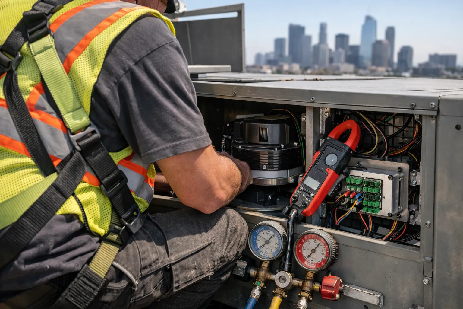
Upgrading existing packaged rooftop units (RTUs) with inverter-driven compressors and electronically commutated (EC) fan retrofit kits is one of the highest‑impact retrofit measures available for small‑to‑mid commercial buildings in 2026. For HVAC enthusiasts and contractors who want practical guidance, this article walks through planning, equipment selection, installation, controls integration, commissioning and performance verification — with concrete checks and common pitfalls to avoid.
Why retrofit RTUs with inverter compressors and EC fans?
Traditional RTUs use fixed‑speed compressors and PSC or induction motors for supply/return fans. Those systems run inefficiently at part load because the compressor cycles and fans run at full speed regardless of demand. Two retrofit levers capture substantial part‑load savings:
- Inverter‑driven compressors (frequency converters or variable‑speed compressor modules) enable continuous modulation of refrigerant flow, reducing cycling losses and improving SEER/IEER at partial loads.
- EC fans replace fixed‑speed motors with electronically commutated motors and integrated variable‑speed drives, allowing precise fan curves to meet static pressure and ventilation with much lower electrical draw.
Together, retrofitting both systems can reduce annual HVAC energy use by a significant amount — typically in the range of 20–40% for many climates and operating profiles, with higher part‑load benefits (30–50%) where units operate continuously at moderate loads.
When to consider a retrofit
- RTU is functional but older (10–20 years) with a still‑sound coil, cabinet, and ducting.
- Building usage has changed to longer run hours or variable occupancy (retail, offices, multi‑family).
- Utility demand charges or time‑of‑use rates make peak reduction valuable.
- Utility rebates or state incentives are available for VFD/EC or inverter retrofits (check local programs in 2026).
- Owner wants improved comfort control and quieter operation without full RTU replacement.
Pre‑project survey: the essential measurements
Before ordering components, gather baseline data. Accurate survey data avoids mismatches that kill payback.
- Unit identification: make/model, nominal capacity (tons), refrigerant type, age, serial number.
- Electrical: supply voltage, starter type, available spare space in electrical compartment, and disconnect rating.
- Operating profile: typical run hours, seasonal loads, thermostat setpoints and staging.
- Performance measurements: supply and return air temps, discharge pressure and suction pressure, amp draw on compressor and fans, static pressure at fan inlet/outlet, and airflow estimates (CFM) using pitot or balometer.
- Mechanical condition: check coils, condensate drain, bearings, belts (if any), and cabinet seals.
Equipment selection: what to buy
Choose components that match the RTU’s mechanical and electrical realities. Two common retrofit approaches:
- Compressor retrofit module — frequency inverter or packaged inverter kit that drives the existing compressor (or a matched replacement compressor engineered for inverter duty). Vendors include OEM retrofit modules and third‑party drives designed for HVAC compressors. Confirm compatibility with the compressor type and refrigerant.
- EC‑fan retrofit kit — direct replacement fan wheel and EC motor assembly (or an external variable drive that controls the existing motor). Choose a kit sized for the RTU fan housing and capable of meeting required static pressures. Leading motor makers (ebm‑papst, Ziehl‑Abegg, etc.) supply retrofit assemblies; select models with integrated speed control and onboard protections.
Also purchase:
- Dedicated controls interface (BACnet MS/TP, Modbus, or analog 0–10 V / PWM) if BMS integration is required.
- Sensors: accurate supply air temp, return air temp, static pressure transducers, and refrigerant temperature/pressure sensors (suction/discharge) for commissioning.
- Electrical components: line reactors, harmonic filters, proper fusing and disconnects sized to drive electronics.
Compatibility checklist
- Compressor type is approved for variable‑speed operation or replaced with one that is.
- VFD/inverter is rated for the compressor motor and refrigerant pressures; vendor confirms refrigerant compatibility.
- EC fan assembly fits physically and meets airflow/static requirements without major duct modifications.
- Electrical service and disconnect are adequate; rooftop weight/structural capacity is confirmed.
- Manufacturer warranty and code compliance are preserved — confirm with RTU OEM whether retrofit voids warranty.
Controls integration strategy
Effective energy savings require coordinated control of compressor speed, fan speed, and the RTU’s economizer and staging logic.
- Primary control objectives: maintain zone temperature, satisfy ventilation, minimize compressor cycling, and maintain coil protection (avoid low‑load frosting in heating modes).
- Integration options:
- Native OEM kit integration: many inverter kits provide built‑in control logic and simple thermostat inputs — fastest for small installs.
- BMS integration: map compressor speed, fan speed, status and alarms to BACnet/Modbus for supervisory demand management and scheduling.
- Local control layering: use local PID loops for suction superheat and supply air temperature, and provide setpoint commands from the BMS (preferred for precise control).
- Control sequences to implement:
- Modulate compressor speed to meet zone load rather than staging multiple compressors.
- Use supply‑air temperature (SAT) control combined with discharge air setpoint for coil protection.
- Run EC fans to a minimum speed to maintain ventilation, then modulate to maintain building static pressure or SAT.
- Implement soft start/stop ramps to avoid inrush and mechanical stress.
Installation checklist (practical steps)
Coordinate rooftop work with mechanical and electrical trades. Key steps:
- Power down and lockout/tagout the RTU. Verify zero energy at the unit.
- Install compressor inverter module or replace compressor with inverter‑rated unit. Mount VFD close to the compressor drive and route shielded motor cables to avoid electrical noise.
- Install EC fan assembly or retrofit motor. Confirm wheel balance, verify directional rotation, and set fan inlet/outlet seals.
- Fit and wire sensors: suction/discharge pressure transducers, compressor motor current sensors, supply/return air temps, and static pressure transducer(s).
- Wire control signals: thermostat/BMS inputs, analog setpoints (0–10 V), and digital fault outputs. Use shielded communication cabling for BACnet/Modbus to minimize noise.
- Update or replace starters and disconnects as required; install line reactors or harmonic mitigation for VFDs if required by local code or utility interconnect rules.
- Perform refrigerant leak test if any brazing occurred; verify charge and pressures per manufacturer guidance for inverter operation.
Commissioning and performance verification
Commissioning is where the retrofit delivers promised savings. Follow a rigorous test protocol:
- Baseline comparison: if possible, capture pre‑retrofit runtime and energy use or use pre‑project data to set expectations.
- Functional tests:
- Confirm that compressor speed varies smoothly and responds to load setpoints.
- Verify EC fan responds to static pressure and ventilation setpoints without hunting.
- Check interlocks: low‑pressure cutout, high‑pressure cutout, motor overcurrent protections, and freeze protection logic.
- Performance measurements:
- Record amp draw and power (kW) for compressor and fan at 25, 50, 75 and 100% commanded speeds.
- Measure airflow (CFM) and static pressure at the operating points.
- Log supply/return temperatures, suction/discharge pressures and superheat at part‑load and peak load.
- Controls tuning: tune PID loops for SAT and suction superheat. Ensure minimum speeds prevent coil frosting during heating and maintain ventilation rates.
- Document settings, compile commissioning report including before/after energy projections and measured kW reductions.
Expected performance and payback
Outcomes vary by climate, unit runtime, and existing control strategy. Typical expectations in 2026:
- Part‑load energy reduction of 30–50% during hours when compressor and fan modulation are active.
- Annual HVAC energy savings commonly 20–40% in systems with long run hours and significant part‑load operation.
- Installed cost range (order‑of‑magnitude): $5,000–$15,000 per RTU for small units (2–5 tons) up to $15,000–$50,000 for larger units (10–25 tons), depending on parts, controls work, and rooftop access complexity.
- Simple payback often 2–6 years after incentives; confirm with measured kWh reductions and utility rates (including demand charges).
Common pitfalls and how to avoid them
- Incorrect compressor match: Not all compressors are suitable for variable‑speed operation. Confirm OEM approval or replace with inverter‑rated compressor.
- Poor control integration: Adding inverters but leaving legacy ON/OFF staging can cause hunting. Implement proper setpoint logic and PID loops.
- Undersized EC fan selection: Choosing a fan that cannot meet required static pressure leads to inadequate airflow and occupant complaints.
- Harmonics and electrical issues: VFDs can create harmonics; mitigate with line reactors, filters or coordinate with utility if required.
- Warranty and code conflicts: Check with RTU OEM and local AHJ about modifications that could void warranty or require permit inspections.
Safety, refrigerant and regulatory notes (2026)
Always comply with local codes and safe refrigerant handling practices. In 2026 the market includes a mix of refrigerants and some RTUs may have transitioned to lower‑GWP blends. Confirm inverter and motor compatibility with refrigerant pressures and safety classifications. Pull permits when required and use certified HVAC technicians for refrigerant work and electrical changes. Check available utility incentives and tax credits — many programs still favor VFD/EC fan and inverter retrofits.
Case example (short)
A 12‑ton RTU on a small retail building in a temperate climate ran ~4,500 hrs/year. Pre‑retrofit measured kW averaged 20 kW at peak. An inverter compressor + EC fan retrofit reduced average HVAC kW to ~13 kW during typical occupied hours and cut compressor cycling by two‑thirds. Measured annual energy savings were ~35%, utility rebates covered ~25% of equipment cost, and simple payback was just under four years.
Closing checklist for project kickoff
- Complete rooftop survey and record all measurements listed in the pre‑project section.
- Obtain OEM retrofit compatibility confirmation and warranty review.
- Specify communication protocol (BACnet/Modbus/0–10 V) and sensors required.
- Secure utility incentive pre‑approval where required.
- Schedule a formal commissioning window and measurement plan with a data logger to capture before/after performance.
Retrofitting RTUs with inverter compressors and EC fans is a practical, scalable pathway to immediate energy and comfort improvements without the capital cost of full unit replacement. With careful surveying, correct component selection, and disciplined commissioning, building owners can capture deep part‑load savings, quieter operation, and better control in 2026 and beyond.