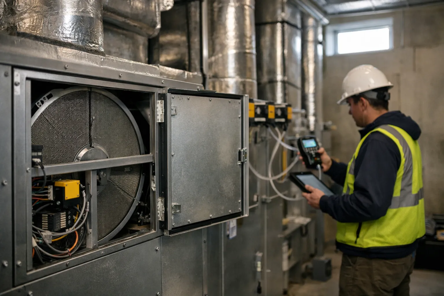
Overview
As multifamily owners and retrofit teams pursue higher energy performance and better indoor air quality, combining a Dedicated Outdoor Air System (DOAS) with decentralized heat pumps (wall‑mounted or compact ducted units) is an increasingly practical strategy. This guide explains, step by step, how to plan, size, install, control and commission a DOAS + decentralized heat‑pump retrofit for mid‑rise multifamily buildings (4–12 stories) in 2026—emphasizing practical choices, code references, and common pitfalls encountered in real projects.
Why DOAS + Decentralized Heat Pumps?
- Decouples ventilation from space conditioning: DOAS handles continuous outdoor air and latent control; heat pumps handle sensible load (heating/cooling) in each unit.
- Simpler refrigerant containment: decentral units limit long refrigerant runs vs central plant or VRF when retrofitting existing buildings.
- Incremental installability: units can be installed unit‑by‑unit during turnover cycles—useful for occupied retrofits.
- Improved IAQ and humidity control: a properly sized DOAS with energy recovery and dedicated dehumidification reduces mold risk and tenant complaints.
Preliminary Assessment: Building & Scope
Start with a concise building survey and scope decision:
- Characterize envelope performance: insulation R‑values, window U‑factors, infiltration rates (blower door results if available).
- Determine occupancy and unit mix: floor area and bedroom count per unit (needed for ASHRAE 62.2 ventilation calculations).
- Decide retrofit extent: all units vs phased, central corridor vs private balconies for outdoor air grilles, and whether corridor pressurization is required by code.
- Identify mechanical room constraints: DOAS location, duct chase availability, condensate routing, and electrical panel capacity.
- Climate and local code drivers: consult ASHRAE 62.2 (residential) or 62.1 (mixed‑use), and the local energy code (IECC 2021/2024 updates). Also check local emissions/benchmarking laws (e.g., municipal building performance standards).
Step 1 — DOAS Sizing & Configuration
Goal: Provide continuous ventilation to meet code and manage latent loads without oversizing sensible capacity.
- Sizing ventilation: Use ASHRAE 62.2 formula for residential units: Q (cfm) = 0.01 × floor area (ft²) + 7.5 × (bedrooms + 1) per unit. Sum unit flows for a centralized DOAS serving multiple units. For mixed‑use amenity spaces use ASHRAE 62.1 values.
- Peak vs continuous: Design for continuous ventilation; provide boost modes for kitchens and bathrooms tied to exhaust fans. DOAS sensible/latent capacity should handle the continuous ventilation dew point and peak humidity conditions—particularly in humid climates.
- Energy recovery device: Choose ERV vs HRV based on climate:
- Climate with significant summer humidity (hot‑humid zones): ERV with appropriate moisture transfer or DOAS with mechanical dehumidification to control latent load.
- Cold, dry climates: HRV preserves indoor humidity and reduces winter sensible load penalty.
- Mixed climates: modern ERVs with balanced sensible/latent performance are generally preferred; validate using psychrometric analysis.
- Conditioning vs dehumidification: If outdoor air latent load exceeds DOAS ERV capability during high humidity, specify a DOAS with cooling coil and dedicated dehumidification control (reheat or enthalpy‑based control) sized to maintain indoor dew‑point targets (often 55–60°F dp in summer).
- Redundancy & serviceability: Use modular DOAS sections so one module can be serviced without full shutdown.
Step 2 — Choosing Decentralized Heat Pumps
Select unit type and features appropriate to building constraints and tenant expectations.
- Unit options:
- Wall‑mounted ductless mini‑splits: low‑cost, easy installation, suitable for room‑level control.
- Compact concealed ducted units (slim duct): better esthetic for certain unit layouts; require short duct runs and plenums.
- Through‑the‑wall packaged heat pumps: useful where exterior penetrations are limited and corridor access exists.
- Capacity & performance: Size for sensible load only (since DOAS handles outdoor air latent load). Use heat‑pump sensible performance at partial load (refer to manufacturer performance tables). Aim for staging or inverter (variable capacity) compressors to avoid short cycling.
- Refrigerant considerations: Keep refrigerant line lengths short; when long runs are unavoidable, plan for proper oil return, factory charge corrections, and local code compliance for A2L refrigerants as required. (Check 2026 refrigerant regulations in your jurisdiction.)
- Controls & communication: Prefer units with BACnet/IP or Modbus integration or use local controllers for heat‑pump thermostat scheduling to coordinate setback and demand response capabilities.
Step 3 — Distribution, Ducting & Install Details
Key to performance: maintain low pressure drops and ensure balanced flows.
- DOAS to units: Options include central plenum with risers to each unit exterior grille, or corridor distribution with transfer ducts into units. Choose the path minimizing invasive work and maintaining fire separations.
- Location of outdoor air intakes: face away from loading docks, bus stops, and sources of contamination; maintain code minimum clearances.
- Acoustics: Use lined ductwork and silencing for DOAS runs through corridors to meet amenity noise limits (NR 30–35 typical in living spaces).
- Condensate: Provide trapped and vented condensate drains and condensate overflow safety switches in DOAS and in‑unit evaporator drip pans; anticipate glycol loops in cold climates where DOAS coils are located outdoors.
Step 4 — Controls & Integration
Controls are where the DOAS + decentralized system delivers energy savings while keeping IAQ consistent.
- Minimum controls scope:
- DOAS: continuous run with CO2 or humidity‑based boost in common spaces (gym, laundry). Include enthalpy/dew‑point controls for dehumidification sequencing.
- Units: programmable thermostats with occupancy setbacks and staging; integrate with building energy management system (BMS) for demand response and preventive alarms.
- Ventilation alarms: monitor differential pressures, filter loading, and ERV wheel lockouts.
- Sequence examples:
- Normal: DOAS supplies required continuous OA; units follow space thermostat for sensible control.
- Boost: Bathroom/kitchen exhaust timers trigger DOAS boost to handle transient loads; dampers modulate supply to maintain balanced pressure.
- Humidity emergency: If RH > setpoint (e.g., 60% RH) call for DOAS cooling/dehumidification and, if available, cropless reheat to avoid overcooling units.
- Data & metering: Meter DOAS airflow, supply/return temps, and electrical energy. Meter per‑unit energy where practical for attribution and benchmarking.
Step 5 — Commissioning & Testing
Proper commissioning ensures expected performance and tenant comfort.
- Pre‑start: Verify installation to submittals—duct insulation, condensate routing, clearances, and electrical supply.
- Airflow balancing:
- Measure DOAS supply and exhaust flows with pitot traverses or calibrated flow hoods; verify per‑unit ventilation flows against design targets (±10%).
- Check pressure relationships (corridor vs unit) to ensure code‑required pressurization and to avoid cross‑contamination.
- HVAC functional testing:
- Sequence tests for normal, boost, humidity emergency modes and controlled reheat cycles.
- Verify heat‑pump staged/inverter modulation under varying loads and check defrost cycles for heating season performance.
- Humidity and dew‑point validation:
- Log indoor temp/RH and supply/return dew points over a week in representative units in summer and shoulder seasons to confirm latent control.
- Controls validation: Confirm alarms, BMS telemetry, setpoint schedules, and demand‑response commands operate as designed.
Common Pitfalls & Troubleshooting
- Undersized DOAS latent capacity: symptoms include elevated indoor RH despite adequate supply CFM—fix by adding dehumidification or increasing ERV effectiveness.
- Unbalanced airflows and corridor pressurization: causes odor transfers and tenant complaints—correct with dampers and supply rebalancing.
- Short cycling heat pumps: often due to oversizing sensible capacity—reduce capacity or add minimum runtime controls and use inverter units.
- ERV wheel icing in cold climates: use preheat coils or ERV bypass to prevent wheel freeze on extreme cold startups.
- Poor maintenance access: locate filters, coils and fans in serviceable rooms and include clear labeling and replacement schedules.
Illustrative Sizing Example
Apartment: 900 ft², 1 bedroom.
- Ventilation (ASHRAE 62.2): Q = 0.01 × 900 + 7.5 × (1 + 1) = 9 + 15 = 24 cfm continuous per unit.
- Building: 60 units × 24 cfm = 1,440 cfm continuous. Add common area ventilation and boost allowance; design DOAS nominally 1,700–1,900 cfm with ERV and a cooling coil sized to handle latent peaks (estimate 0.5–1.0 ton of sensible cooling plus latent capability—verify with psychrometric load analysis for local summer conditions).
- Distribution: use 1,700 cfm DOAS feeding 60 supply risers (~28 cfm each) with balancing dampers at each riser. Provide per‑unit transfer grille or short run to living space with sound attenuation.
Checklist for Implementation
- Confirm applicable code: ASHRAE 62.2 vs 62.1, local IECC, and municipal performance standards.
- Site survey: envelope, chases, mechanical rooms, electrical capacity.
- DOAS selection: airflow, ERV/HRV decision, cooling/dehumidification coil, modularity.
- Unit selection: type, capacity, inverter capability, controls comms.
- Ductwork planning: fire separations, acoustics, condensate routing.
- Control sequences: continuous ventilation, boost modes, humidity response, schedules.
- Commissioning plan: acceptance tests, airflow balancing, dew‑point logging, control verification.
- Maintenance plan: filter schedules, ERV wheel cleaning, condensate checks, refrigerant leak detection frequency.
Real‑World Context & Next Steps (2026)
In 2026, many jurisdictions have tightened ventilation and energy requirements; integrating a DOAS with decentralized heat pumps can help projects comply with stricter ventilation rates while still meeting electrification and decarbonization goals. Expect to coordinate with utility incentive programs for high‑efficiency DOAS and inverter heat pumps, and to document IAQ improvements in tenant communications.
For teams planning such retrofits, the next steps are a targeted feasibility study (1–2 weeks), followed by a detailed mechanical design and a commissioning plan. Engage a commissioning authority early and allocate contingency for unexpected field conditions common in occupied retrofits.
Bottom line: A properly sized DOAS paired with decentralized heat pumps provides robust IAQ, humidity control, and phased installation flexibility for multifamily retrofits. Success depends on correct DOAS latent sizing, thoughtful distribution design, and commissioning that verifies both airflow and dew‑point control under real operating conditions.