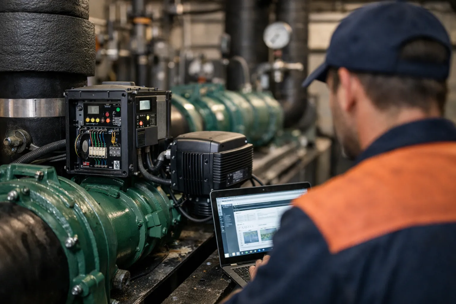
Retrofitting chilled‑water pumps with variable‑frequency drives (VFDs), electronically‑commutated motors (ECMs) and modern control algorithms is one of the highest‑value efficiency upgrades an HVAC systems enthusiast or facility engineer can undertake. When done correctly, pump retrofits reduce energy use, lower wear on mechanical components, and improve the control of chilled‑water distribution—often with paybacks of 1–4 years depending on run hours and plant design.
Who this guide is for and what it covers
This practical, step‑by‑step guide is intended for HVAC systems enthusiasts, facility engineers and contractors planning a chilled‑water pump retrofit in commercial or institutional plants (small to medium chilled‑water plants, 50–1,000+ tons). It focuses on centrifugal pumps feeding chilled‑water systems and covers:
- How to assess baseline performance and energy use
- Pump and motor replacement vs. VFD retrofit vs. ECM upgrade
- Control strategies (ΔP reset, flow measurement, cascade with variable primary/secondary)
- Installation best practices, electrical and harmonics considerations
- Commissioning tests and acceptance criteria
- Operating, maintenance and ROI example
Why retrofit? The opportunity in numbers
Pumping accounts for a large share of chilled‑water plant energy—commonly 15–30% of building HVAC electricity. Because pump power varies with the cube of speed (affinity laws), modest flow reductions via VFDs and controls can yield large energy savings. Example: reducing pump speed by 20% cuts power by roughly 49% (0.8³ ≈ 0.512). Real savings depend on system curve, throttling, and pump oversizing.
Prerequisites and safety
Before starting: obtain hydraulic drawings, pump curves, motor nameplate data and BAS integration details. Ensure electrical capacity and short‑circuit studies are available. Work with licensed electricians for power changes, follow NFPA 70/NEC requirements, local codes and manufacturer instructions. Confirm lockout/tagout and confined space protocols where applicable.
10-step retrofit workflow
-
Step 1 — Baseline assessment and metering
Measure current performance for at least two weeks (ideally full seasonal coverage). Install temporary power loggers on pump motors (kW), and monitoring for suction/discharge pressure, motor current, and chilled‑water flow or ΔT on a representative branch. Determine hours of operation and load profile. Calculate baseline annual energy use (kWh) and demand (kW).
-
Step 2 — Hydraulic survey and system curve
Develop or verify the system curve: measure flow at several pump speeds or operate the pumps in different configurations to plot head vs. flow. If flow meters aren’t permanent, use calibrated ultrasonic clamp meters or portable insertion meters. Identify throttling devices (control valves, bypasses) and any system anomalies like closed valves or blocked strainers.
-
Step 3 — Decide retrofit approach: VFD vs. motor replacement vs. full pump swap
Options:
- Install VFD on existing motor when mechanical condition is good and motor is compatible (typically ≥4 pole motors benefit more).
- Replace motor with an ECM or premium IE3/IE4 motor and pair with VFD for best efficiency at part load—ECMs on larger centrifugal pumps are less common but emerging.
- Replace pump with a smaller, properly sized pump with VFD if the existing unit is severely oversized.
Use affinity laws and measured system curve to model expected operating points and energy savings. Check NPSH availability for new operating speeds.
-
Step 4 — Select VFD and electrical components
Key VFD specifications:
- Rated for motor full‑load current plus margin
- Proper voltage class and enclosure rating (NEMA 1/12/3R as required)
- Low harmonic or include harmonic mitigation (AC filters or multi‑pulse drives) if harmonics risk exists
- Regeneration capability if system demands rapid deceleration
- Support for PID inputs, BACnet/MSTP or Modbus and optional Ethernet/IP for BMS integration
Include bypass/contactors for maintenance and code‑required disconnects. Verify short‑circuit current rating and protective device coordination.
-
Step 5 — Sensors and control architecture
Decide control variables: common strategies are constant‑pressure (ΔP) with setpoint reset, differential temperature (ΔT) monitoring for flow confirmation, and flow‑based control with magnetic flow meters where precision is needed.
Sensor placement and selection:
- Pressure transducers: 0–150 psi typical range; install both suction and discharge taps upstream of valves/bends, use static tees
- Flow meters: full‑bore mag meters for accuracy; ultrasonic clamp meters for temporary checks
- Temperature sensors: RTDs in insulated pockets for entering and leaving chilled water to validate ΔT
Control topology examples:
- ΔP reset: BAS computes required ΔP setpoint ramp as plant load falls—commonly 20–50% reset range
- Cascade control: Pump VFD follows a primary sensor (ΔP) while BAS optimizes setpoint based on chiller staging
- Flow‑based control: VFD maintains measured flow when precise distribution is required
-
Step 6 — Mechanical and piping considerations
During installation:
- Check alignment and shaft coupling if reusing the pump—correct misalignment to avoid vibration
- Maintain straight run requirements around flow meters (manufacturer spec, often 5–10 D upstream)
- Install isolation/suction/discharge valves and a bypass/recirculation line sized for minimum flow to protect pump from low‑flow conditions
- Include vibration isolation pads and flexible connectors to avoid piping stresses
-
Step 7 — Electrical installation and harmonics mitigation
Wire per NEC and VFD manufacturer guidance. Consider harmonic mitigation when multiple VFDs or sensitive equipment exist: options include 12‑pulse or 18‑pulse converter configurations, active front‑end (AFE) drives, or line reactors. Confirm cooling of VFDs—ventilation or heat rejection may be necessary in cramped electrical rooms.
-
Step 8 — Control programming and BAS integration
Implement control sequences: soft start, ramp limits, PID tuning, loss‑of‑flow and dry‑run protection, and fault handling. Expose key points to BAS: commanded speed, actual speed, motor current, suction/discharge pressure, flow, and alarms. Use secure protocols (BACnet/IP, BACnet MSTP with secure gateway) and follow cyber hygiene guidance for controllers and remote access.
-
Step 9 — Commissioning and performance validation
Commissioning tests should include:
- Pump curve verification: measure head and flow at multiple speeds and compare to manufacturer curve
- System curve confirmation and operating point mapping
- ΔP reset validation: demonstrate energy savings across part‑load points and that ΔT constraints are respected
- Electrical acceptance: harmonics, inrush, motor current, temperature rise
- Vibration and NPSH checks
Document baseline vs. post‑retrofit energy use using the same measurement points used for baseline. Validate expected kWh reduction and calculate actual payback.
-
Step 10 — Operations, maintenance and continuous optimization
Train operations team on new sequences, alarm responses and preventative maintenance (filter/strainer cleaning, bearings, alignment). Establish routine trending of motor power, flow and ΔT and schedule periodic PID retuning. Use BAS analytics or simple dashboards to track performance drift and identify fouling, valve changes or sensor faults.
Practical ROI example (realistic scenario)
Facility: 600‑ton chilled‑water plant with two primary pumps and two secondary pumps. Baseline pumping load: 200 kW average during occupied hours (12 hrs/day).
Retrofit: install VFDs on four pumps; tighten control with ΔP reset and verify reduced throttling. Modeled average pump power drops to 95 kW—savings 105 kW during occupied hours.
- Annual occupied hours (250 days × 12 hrs) = 3,000 hrs
- Annual energy saved = 105 kW × 3,000 hrs = 315,000 kWh
- At $0.12/kWh, value = $37,800/yr
- Project installed cost (VFDs, sensors, controls) = $110,000 → simple payback ≈ 2.9 years
Actual site results often vary; always use measured baseline data and conservative assumptions for payback calculations.
Common pitfalls and how to avoid them
- Oversized pumps left unchanged: if the pump is grossly oversized, adding a VFD alone can still waste energy—consider pump resizing.
- Poor sensor placement: noisy or poorly located pressure taps produce unstable control—use proper taps and signal filtering.
- Ignoring harmonics: can cause equipment upset or utility penalties—evaluate and mitigate.
- Insufficient minimum flow protection: running below recommended flow causes recirculation damage—ensure bypass or minimum speed.
- No post‑installation monitoring: without trending, faults or drift will erase savings—implement dashboards and alarms.
Regulatory and specification notes (April 2026)
As of 2026, many jurisdictions and incentive programs prioritize motor and drive upgrades. Consult local utility rebates (which often require pre‑ and post‑installation metering) and reference ASHRAE guidance on control sequences. For large projects, align specifications with ANSI/HI pump standards and IEEE 519 for harmonics control.
Closing checklist
- Baseline energy and system curve documented
- Selected VFD and motor meet electrical and harmonics requirements
- Sensors sized and located per manufacturer guidance
- Bypass/minimum flow protection installed
- BAS integration and secure communications implemented
- Commissioning plan with acceptance tests and measurement verification
- Operations training and monitoring dashboards in place
Retrofitting chilled‑water pumps with VFDs and modern controls is a proven path to substantial energy and operational gains. The key to success is measurement‑driven decision making: start with a good baseline, verify the hydraulic conditions, select equipment to match the system, and commit to commissioning and monitoring after installation. That discipline turns potential savings into reliable, sustained performance.