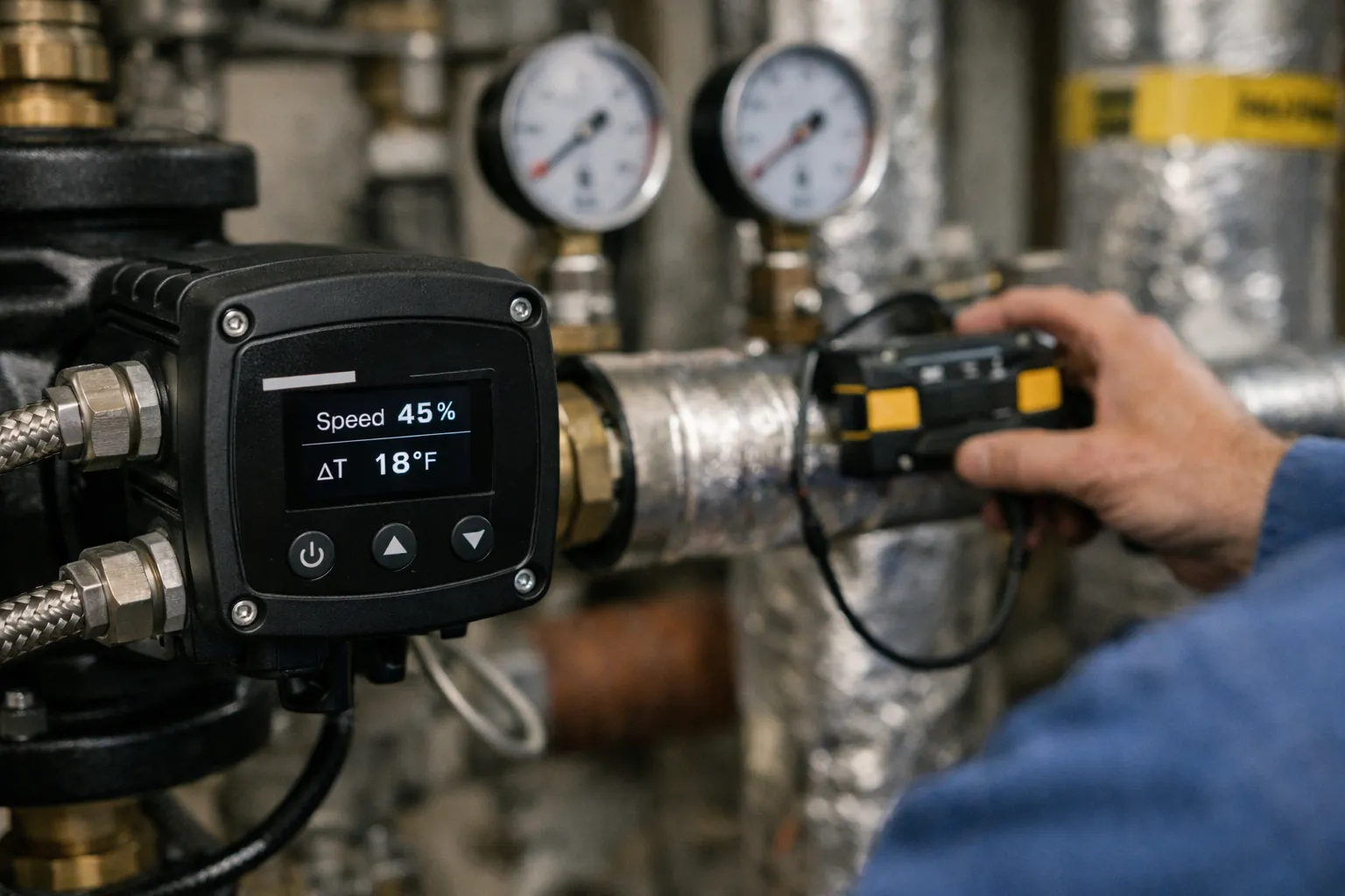
Overview: Why convert constant‑flow hydronic systems to variable‑primary?
Many buildings still operate with constant‑flow hydronic heating delivery: pumps run flat out, valves throttle, and ΔT across the heat source collapses. That pattern wastes pumping energy, reduces heat transfer effectiveness, complicates balancing, and limits modern control strategies. Converting to a variable‑primary pumping approach — using electronically commutated motor (ECM) pumps or VFDs with ΔT control and proper hydraulic arrangements — restores design ΔT, reduces energy use, and simplifies control integration.
What this guide covers
This step‑by‑step guide walks HVAC technicians and system enthusiasts through assessment, design, equipment selection, piping changes, controls programming, commissioning tests and common pitfalls when retrofitting a legacy constant‑flow hydronic heating system to variable‑primary operation. Practical examples and checklists are included so you can apply the method on real projects.
Step 1 — Site assessment and baseline data collection
Before changing pumps or controls, collect accurate field data. The retrofit design depends on real loads, actual piping layout and how loads vary.
- Inventory equipment: boilers/heat sources, radiators/convectors/air handlers, expansion tanks, existing pumps (make/model, horsepower, speed), valves, zone controllers.
- Measure operating conditions: supply and return temperatures at the heat source, flow rates (if accessible), and pump electrical parameters (voltage, current, speed).
- Log ΔT during representative operating periods (morning warm-up, design-day cold, part‑load). If you can’t measure flow directly, measure ΔT and calculate flow using the heat equation (below).
- Note piping geometry: long risers, series-connected elements, number of parallel zones, presence of bypass valves or pressure-independent control valves (PICVs).
Quick calculation: estimate existing flow
Use the standard heating heat‑transfer formula for water systems in US customary units:
GPM = BTU/hr ÷ (500 × ΔT°F)
Example: A building zone with a 200,000 BTU/hr boiler load and measured ΔT of 10°F has:
GPM = 200,000 ÷ (500 × 10) = 40 GPM
If you can increase ΔT to 20°F (by reducing flow), the required flow becomes 20 GPM — a 50% reduction in pump work potential.
Step 2 — Decide hydraulic approach: variable‑primary vs. primary‑secondary
Two common retrofit strategies:
- Variable‑primary pumping: A single variable‑speed pump or pump bank varies flow to meet load. Often simplest when zones are already decoupled or when loads are mostly parallel.
- Primary‑secondary (decoupled) with a hydraulic separator: Keep a constant primary flow through the boiler loop and add a variable secondary system for zones. Useful if the boiler needs minimum flow or existing piping is closely coupled.
Which to choose?
- Choose variable‑primary when the boiler can tolerate varying flow (most modern boilers can), or when a small hydraulic separator can be installed to prevent unwanted interactions.
- Choose primary‑secondary if the heat source manufacturer requires minimum flow, or when older boilers need thermal stability to avoid condensation or cycling.
Step 3 — Pump selection and sizing
Upgrading to an ECM pump or VFD‑controlled centrifugal pump is central. Follow this sequence:
- Calculate required maximum design flow using peak loads and target ΔT at design conditions (use GPM = BTU÷(500×ΔT)).
- Estimate system head: measure or calculate friction losses using pipe lengths, fittings, and terminal device resistance. If data are incomplete, use a measured method (see commissioning tests below) or conservative estimates based on pipe schedule and flow.
- Select a pump whose best efficiency point (BEP) is near the expected operating flow and head. For ECMs, choose one with integrated variable speed and a control input for ΔP or flow control.
- Confirm motor protection, NEMA enclosure, and pipe connections match the mechanical room. For multicircuits, consider multiple ECM pumps staged or a pump with automatic lead/lag.
Sizing example
Continuing the earlier example: design load 200,000 BTU/hr, target ΔT 20°F → 20 GPM. If calculated friction head at 20 GPM is 25 ft of head, select a pump curve that delivers 20 GPM at ~25 ft and has good turndown to 5–10 GPM. Modern ECMs can modulate widely and maintain efficiency.
Step 4 — Piping and hydraulic modifications
Common piping changes include adding a hydraulic separator, removing or modifying bypasses, and ensuring proper air elimination and trapping.
- Hydraulic separator / decoupler: If you choose primary‑secondary, install a properly sized hydraulic separator between boiler and distribution loops. Follow manufacturer sizing charts (volume must allow flow separation at maximum anticipated flow).
- Remove permanent bypasses: Old systems may include bypasses that defeated control. Replace with controllable bypass or eliminate if not required.
- Balance valves and PICVs: Add or verify balancing valves. Consider pressure‑independent control valves on critical terminal units to prevent interaction when flow varies.
- Air and dirt removal: Install automatic air vents, dirt separators, and magnetic traps when relocating pumps or adding VFDs to prevent cavitation and blockages.
Step 5 — Controls: ΔT reset, pressure/flow control and system protection
Control strategy defines success. Typical control elements:
- ΔT control loop: Use an outdoor reset or load‑based reset to adjust supply temperature. Use pump speed control to maintain a target ΔT or a differential pressure setpoint that follows valve positions.
- Pump control modes: Consider PID control for ΔT, or use differential pressure control with setpoint profiling (e.g., DP setpoint reduces with part load). Modern ECM pumps accept 0–10V/4–20mA or Modbus/BACnet for speed reference.
- Minimum flow protection: Implement a minimum speed or bypass to maintain boiler minimum flow and avoid condensation on low‑mass boilers.
- Soft starts and anti‑short‑cycling: Coordinate pump and boiler controls to prevent frequent cycling. Use run timers and minimum on/off times.
- Integration with BMS: Expose pump status, speed, ΔT, and alarms to the building automation system for trend logging and remote tuning. Utilities increasingly require data for rebate programs.
Step 6 — Installation best practices
Follow these practical tips during the physical retrofit:
- Install pumps with correct orientation: Ensure suction piping has minimal turbulence and close‑coupled connections are tight.
- Provide isolation valves, flanges, and unions to allow future replacement without draining the system.
- Mount vibration isolation and provide a service platform if the pump is heavy.
- Run control wiring in separate conduit from power wiring to minimize interference; follow manufacturer wiring diagrams for ECM analog/digital inputs.
- Label new devices clearly and update mechanical room documentation, piping schematics and control narratives.
Step 7 — Commissioning and performance verification
Commissioning ensures the retrofit delivers the promised ΔT improvement and energy savings. A structured test plan:
- Flush and fill the system, perform chemical cleaning if needed, and vent air thoroughly.
- Record baseline electrical consumption (pump kW) for comparison.
- With the building at steady state, measure supply and return temps at the boiler and at remote terminals. Verify achieved ΔT at design and part‑load periods.
- Measure flow using a clamp‑on ultrasonic flow meter or by measuring differential pressure across a known orifice or plate to confirm flows match design.
- Verify pump curve performance: record pump speed, amps, and calculate hydraulic power. Confirm pump operates in efficient region across load range.
- Test control sequences: simulate zone loads and verify pump speed changes and ΔT response. Test minimum flow protections and boiler interlocks for safe operation.
- Document results, trend data, and recommended control tuning parameters. Compare energy use to baseline and estimate payback.
Commissioning checklist (summary)
- ΔT measurements at design and part‑load
- Flow verification (GPM)
- Pump electrical draw and efficiency check
- Control setpoint and alarm validation
- Hydraulic stability: no noise, no cavitation, no vapor locks
- Air/dirt separator performance
Expected energy and operational impacts
Typical ECM retrofits in hydronic heating can reduce pumping energy by 40–70% depending on the original system inefficiency and how aggressively ΔT is recovered. Additional benefits:
- Improved zone control and faster temperature recovery
- Extended pump life due to softer start and reduced full‑speed run time
- Reduced boiler short cycling if control integration is correct
- Lower maintenance associated with fewer throttled valves and reduced thermal stress
Quantify savings using metered electrical data and ΔT logs during the first winter season to validate assumptions used in payback calculations. Many utilities and state programs in 2026 offer rebates for ECM pump retrofits and controls — check local incentive portals.
Common pitfalls and how to avoid them
- Ignoring minimum boiler flow: Confirm boiler manufacturer requirements. If minimum flow is required, provide a small constant bypass or adopt primary‑secondary design.
- Poorly sized pumps: Oversized pumps operating far right of BEP will waste energy and can be noisy. Use accurate head curves or field measurements to size correctly.
- Unmanaged bypasses: Existing bypass valves can defeat variable pumping — remove or control bypassing valves.
- Insufficient air/dirt removal: New variable flow can mobilize debris; install proper separators and strainers.
- Inadequate controls integration: Failing to modify boiler logic and zone controls leads to unintended cycling or low ΔT. Commission control interlocks carefully.
Timeline and ballpark costs
Small commercial or multi‑family retrofits typically follow this schedule:
- Site assessment & design: 1–2 weeks
- Equipment procurement: 2–6 weeks (depends on ECM lead times)
- Installation: 1–4 days for small systems; up to 2 weeks for complex piping changes
- Commissioning & tuning: 2–5 days
Costs vary widely. A single ECM pump replacement for a medium building (including controls and commissioning) often ranges from $3,000 to $10,000 installed. Larger systems with hydraulic separators and substantial piping work can be $15,000–$50,000+. Incentives can improve payback to 1–4 years in many regions.
Final recommendations
Converting constant‑flow hydronic systems to variable‑primary pumping is one of the highest‑impact mechanical retrofits for older buildings. With careful assessment, correct pump and control selection, and thorough commissioning, you can restore design ΔT, cut pumping energy, simplify balancing, and enable smarter controls.
Start with good field data, respect boiler minimum flow requirements, and ensure the controls team programs ΔT and safety interlocks correctly. Meter and trend performance after commissioning — the data will confirm savings and guide future tuning.
Quick-action checklist before you leave the job
- As‑left ΔT and flow measurements logged
- Pump speed/amps at low, mid and high loads recorded
- Control setpoints and BMS points documented and labeled
- Maintenance instructions provided: air separator cleaning, strainer checks, firmware updates
- Rebate paperwork submitted (if applicable)