
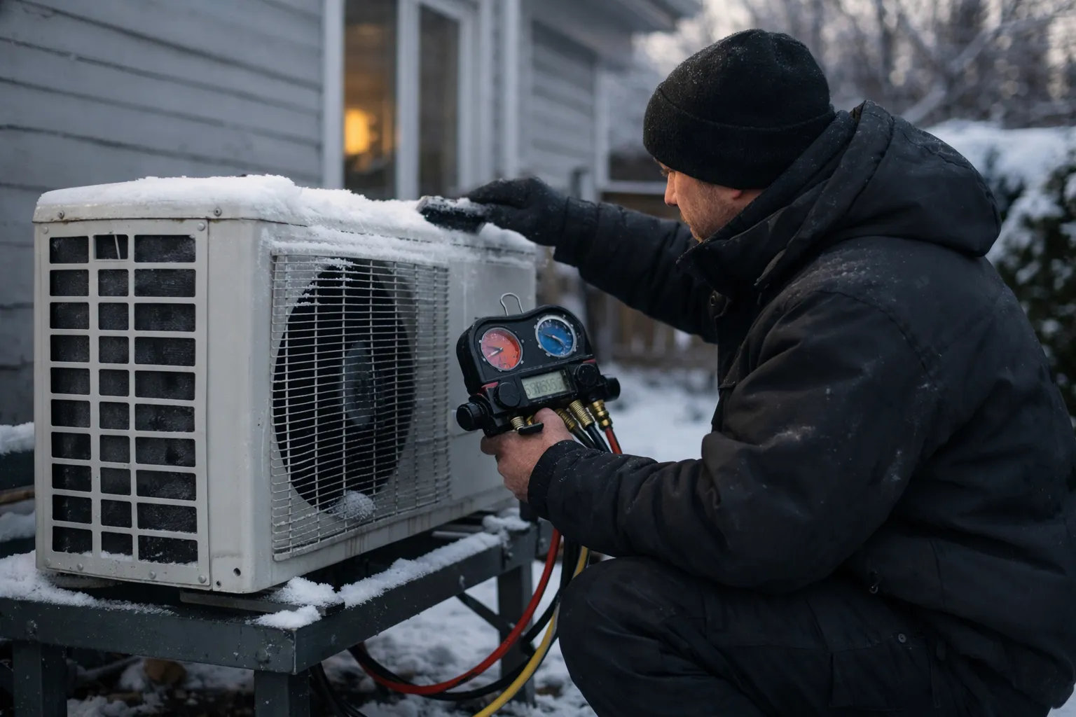
What you'll learn: how to choose and commission a cold‑climate heat pump in October 2026—using verifiable low‑temperature capacity, commissioning discipline, and pragmatic design choices rather than marketing language. This update is written for HVAC enthusiasts, specifying contractors, and technically minded homeowners who expect documented performance, quiet operation, and low winter intervention.
Why this matters now: the industry transition that began in 2022–2024 has continued into 2026. Manufacturers are routinely supplying extended low‑temperature performance tables, lower‑GWP refrigerants are mainstream across most product families, and firmware/control logic is now an explicit part of system performance. Simultaneously, utility pilots and incentive programs have matured, increasingly requiring AHRI‑matched low‑temperature capacity or explicit commissioning deliverables for rebates. That changes how you evaluate a cold‑climate system: firmware, monitoring, and commissioning matter as much as compressor maps.
Prerequisites and context: what “cold‑climate” means in October 2026
“Cold‑climate heat pump” remains an industry shorthand, not a regulated product class. Practically, it means inverter‑driven air‑source equipment designed to retain usable heating capacity through single‑digit and sub‑zero Fahrenheit points for matched outdoor/indoor pairings. By October 2026 it is routine to obtain certified net capacity and COP tables that include points at 47°F, 17°F, and the local 99% design temperature — turning spec verification into a solvable, documented process.
Two context points to keep front of mind:
- HSPF2 and SEER2 are still the seasonals to use. Don’t compare legacy HSPF/SEER values to the “2” versions without conversion — many incentive programs now explicitly require HSPF2/SEER2 numbers in applications.
- Incentive and program rules shape available inventory. Federal tax credits and an increasing number of state/utility rebates now tie eligibility to documented low‑temperature capacity or to commissioning deliverables (for example, AHRI‑matched capacity at the local 99% temperature or submission of a commissioning packet).
Luxury note: the hallmark of a premium cold‑climate installation remains invisibility: consistent indoor temperatures, exceptionally quiet operation, and a system that rarely needs occupant‑level adjustments.
Step 1: Start with design temperatures — not marketing copy
- Find your official winter design temperature. Use ASHRAE/ACCA data in your Manual J tool and document whether you used 99% or another percentile. Many programs explicitly require the 99% design temperature as the sizing baseline.
- Set a clear no‑resistance target. Decide the outdoor temperature at which you require the heat pump to meet full load without auxiliary resistance. In true cold climates this will be the 99% temperature; in milder areas you may accept a lower threshold with planned, limited backup.
Example: for a home in Burlington, VT with a 99% design temperature of 5°F, specify that the AHRI‑matched net heating capacity at 5°F equals or slightly exceeds the Manual J load after accounting for duct/export losses.
Step 2: Obtain a true heating load (Manual J) and verify inputs
Sizing remains decisive; inverter equipment changes the shape but not the math.
- Commission a full Manual J and archive it. Include wall R‑values, window U‑factors, infiltration (ACH), internal gains, thermostat setpoints, and the selected design temperature.
- Sanity‑check envelope and infiltration inputs. Compare the Manual J assumptions to blower‑door results or recent infrared scans if available; over‑assumed losses lead to oversizing and excess defrosts.
- Cross‑check against energy history. Convert winter utility bills into delivered heat (kWh or therms) to validate the Manual J ballpark before equipment selection.
Why this matters: oversizing increases defrost cycles and reduces part‑load efficiency. The goal is a heat pump whose certified capacity curve aligns with the Manual J load profile across typical winter hours, not a larger nameplate.
Step 3: Verify low‑temperature capacity from independent sources
By 2026 most reputable manufacturers publish extended capacity/COP tables for matched outdoor‑indoor combinations; AHRI listings and third‑party directories remain the most reliable cross‑checks.
- Use AHRI and third‑party directories first. Confirm the AHRI reference number for the exact outdoor/indoor combination you will install; that listing should include certified net heating capacities at specified low temperatures.
- Obtain the matched pairing’s extended table. Performance depends on the outdoor unit plus the specific indoor coil or air handler — request the extended capacity/COP table for that pairing, not a generic outdoor unit spec.
- Confirm capacity at your design temp. Look for certified net heating capacity at 47°F, 17°F, and your design temperature; collect COPs at those same points to estimate operating cost and auxiliary reliance.
What to look for: capacity retention (percent of rated capacity at your design temp), the system’s minimum and maximum modulation range, and whether data are measured (AHRI) or manufacturer modeled with third‑party validation. Many incentive programs now reject modeled‑only data for rebate eligibility.
Step 4: Compare efficiency properly — HSPF2, COP, and part‑load behavior
HSPF2 is useful for seasonal comparisons, but COP and part‑load curves reveal winter behavior.
- Use HSPF2 for apples‑to‑apples seasonal comparison across similar architectures (ducted vs ductless).
- Demand COP at specific low temps. Request COP at 47°F, 17°F, and your design temperature. Instantaneous COP governs operating cost and whether auxiliary heat will run.
- Prioritize part‑load control and minimum capacity. Examine whether the unit can modulate into the range most winter hours require. Units with very low minimum capacity (high turndown) maintain steady indoor temps and avoid frequent defrosts.
Rule of thumb: systems whose capacity curve keeps them primarily within roughly 30–100% of output during most winter hours deliver smoother temperatures and fewer defrost cycles than systems that spend long periods near extreme ends of their modulation range.
Step 5: Scrutinize defrost logic, controls, and low‑temp comfort
Defrost strategy is the lived experience. Since 2024 manufacturers have moved more logic into firmware; by 2026 firmware choices materially change defrost frequency and occupant comfort.
- Ask for the defrost flowchart and commissioning log capability. Demand‑based defrost that uses outdoor coil sensors, head‑pressure algorithms, or predictive models outperforms fixed timers in field pilots.
- Understand indoor behavior during defrost. Confirm whether the indoor fan continues, whether the system uses auxiliary heat for recovery, and typical defrost duration and recovery profiles; require these behaviors be demonstrated at commissioning.
- Plan outdoor unit siting carefully. Elevate units above snow‑drift lines, maintain unobstructed airflow, and design melt drainage to avoid re‑freeze at the base.
Commissioning requirement: require the installer to record and provide a sample defrost event and recovery log from the initial commissioning period so you can see indoor recovery behavior in real operation.
Step 6: Ducted, ductless, or hybrid—decide by building architecture
Distribution choice should follow building constraints and performance, not aesthetics alone.
- Ducted works when ducts are sized, sealed, and insulated—verify static pressure and measured airflow at supply grilles during commissioning.
- Ductless offers precise zoning and strong part‑load performance; it is often preferable in retrofit or high‑ceiling spaces where ducts are impractical.
- Hybrid pairings (ducted main with ductless supplemental zones) are common and effective when tailored to occupants’ use patterns.
Test: if existing ducts show static pressure >0.3 in. w.c. at the air handler (or if ducts are >15 years old with unknown sealing), treat them as a risk and budget for remediation or a hybrid approach.
Step 7: Plan backup heat intentionally and avoid waste
Backup is a control tool. The objective is rare, deliberate invocation.
- Choose backup by economics and preferred controls. Electric resistance is simple and reliable but expensive on a per‑kWh basis; dual‑fuel remains an option where fuel economics and emissions tradeoffs justify it.
- Set explicit lockouts and staging. Use outdoor‑temperature lockouts, staged auxiliary logic, and thermostat firmware that recognizes heat pump operation to prevent unnecessary strip‑heat events.
- Verify thermostat wiring and program logic. Miswired controls and default thermostat settings are still the most common cause of unnecessary auxiliary use; require wiring diagrams and commissioning screenshots.
Rule: set auxiliary lockouts conservatively, run a cold‑weather test, and review controller logs after the first real cold snap to confirm limited auxiliary events.
Step 8: Treat contractor selection like commissioning a precision instrument
Installation quality is the decisive variable. Expect detailed commissioning documentation and recorded data.
- Require documented commissioning and a signed packet. This should include refrigerant charge verification or adaptive charge method, measured airflow, static pressure, thermostat configuration screenshots, and recorded control settings.
- Confirm AHRI‑matched installation. The installed indoor/outdoor combination must match the AHRI or manufacturer reference used for capacity verification.
- Demand initial remote monitoring. A 60–90 day monitoring period capturing runtime, defrost events, and auxiliary use is common in higher‑end projects and required by many incentive programs.
- Clarify warranty and firmware policies. Document who controls firmware updates, whether owner authorization is required, and how rollback is handled if an update degrades performance.
Practical expectation: a quality installer will hand you a commissioning packet containing measured refrigerant pressures, airflow numbers, thermostat settings, AHRI reference numbers, and an initial monitoring export with baseline firmware versions recorded.
New October 2026 considerations that change selection
- Lower‑GWP refrigerants are widely adopted. R‑32 and R‑454B are common across many product families; verify service‑tool compatibility and local technician training before committing to a refrigerant that is new to your market.
- Firmware is now a defined performance element. Manufacturers routinely issue firmware that adjusts defrost logic, compressor maps, and grid features. At commissioning, record firmware versions and require owner consent for any changes that affect control logic.
- Grid‑interactive and TOU features are practical value sources. Many utilities now offer time‑of‑use or demand‑response programs that pay for simple preconditioning, staged operation, or remote load curtailment. When available, these features can materially reduce operating costs over a winter season.
- Thermal buffering is more commonly used. Small buffer tanks (10–30 gallons) or insulated plenum buffers reduce short cycling and smooth defrost cycles—particularly useful in ducted hydronic hybrids or for large homes with lower‑GWP systems and tighter charge management.
- Remote monitoring and analytics are expected on higher‑end installs. Dashboards that report runtime, defrost frequency, auxiliary events, and firmware version are now standard deliverables on premium projects and often a rebate requirement.
Common mistakes to avoid
- Buying based on nominal tonnage without verified capacity at your design temperature.
- Mixing HSPF and HSPF2 (or SEER and SEER2) in comparisons.
- Overlooking duct static pressure and airflow constraints.
- Allowing auxiliary heat to trigger because of default wiring or thermostat firmware assumptions.
- Assuming “cold‑climate” marketing replaces AHRI‑matched capacity tables and documented commissioning.
Pro tips (the enthusiast edition)
- Ask for the table, not the brochure. Request the extended capacity/COP charts for the exact matched pairing and the AHRI reference number; save PDF copies in your project folder.
- Document refrigerant specifics and service readiness. Know the refrigerant type, required service tools, and local technician certifications; lower‑GWP is advantageous only when supply and service exist locally.
- Insist on initial remote monitoring. A 60–90 day remote‑monitoring period after commissioning catches control drift and unnecessary auxiliary use early and is often required by incentive programs.
- Consider modest thermal buffering. A 10–30 gallon buffer or an insulated plenum for large ducted systems reduces short cycling and smooths defrost recovery.
- Keep firmware and commissioning records. Store firmware version numbers, commissioning logs, and thermostat screenshots—these reduce finger‑pointing if performance questions arise.
FAQ
How can I tell if a heat pump will actually heat my house at 5°F?
Obtain a Manual J sized to your 5°F (or local 99% design) temperature. Then request the certified net heating capacity for the exact outdoor/indoor combination at that temperature (AHRI listing or equivalent). Cross‑check the COP at that point to estimate operating cost and expected auxiliary use; if the certified net capacity meets or slightly exceeds the Manual J load, the unit should carry the home at that temperature without resistance heat. Require this verification in writing and include the AHRI reference in the commissioning packet.
Should I worry about firmware and automatic updates?
Yes. Since 2024 manufacturers have used firmware to refine defrost logic, modulation, and grid features. At commissioning, record the firmware version, ask about the update policy, and require owner authorization for control‑affecting updates. Also require that the installer validate system behavior after any firmware change and provide rollback capability if performance degrades.
Are low‑GWP refrigerants ready for cold‑climate systems?
Many modern cold‑climate product lines now use lower‑GWP blends such as R‑32 and R‑454B. They perform well when installed and serviced correctly, but confirm local service capability, parts availability, and compatible gauges/hoses before selecting a refrigerant that’s new to your market. In tight supply‑chain regions, the convenience of conventional refrigerant servicing can still matter.
Will adding a larger heat pump eliminate the need for backup heat?
Not necessarily. Oversizing can increase defrost frequency, reduce part‑load efficiency, and still require auxiliary heat depending on thermostat logic. The objective is a match between the Manual J design load and the certified low‑temperature capacity of the matched pairing—oversizing the nameplate is not a substitute for proper spec verification and commissioning.
How should I verify an install once it’s complete?
Require a commissioning packet that includes: measured refrigerant pressures or verified charge method, measured airflow and static pressure (for ducted systems), thermostat wiring and configuration screenshots, the AHRI reference for the matched pair, an initial runtime/defrost log, and the baseline firmware version. Ask for a guided walkthrough of the monitoring dashboard and a copy of the monitoring export for your records.
Sources and reference types: This guide synthesizes industry practice and field experience through 2026: AHRI certified directories for matched combinations; ACCA Manual J methodology for sizing; utility pilot and incentive program requirements tied to commissioning; and contractor commissioning best practices. Always verify current federal, state, and utility product eligibility pages and program technical requirements before purchase or application.