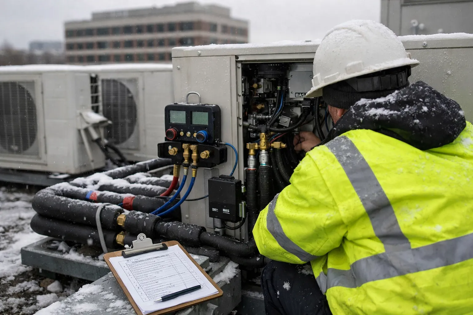
As electrification and low‑GWP refrigerant options accelerate in 2026, hybrid solutions that pair heat‑recovery VRF (variable‑refrigerant‑flow) systems with low‑ambient air‑source heat pumps (ASHPs) are an increasingly practical retrofit pathway for cold‑climate commercial buildings. This guide walks HVAC enthusiasts through a complete, actionable process—from site assessment and system selection to piping, controls integration, commissioning and long‑term operation—focusing on the real‑world constraints you’ll face in retrofit projects.
Why choose a hybrid VRF + low‑temp ASHP retrofit?
- Heat‑recovery VRF lets zones simultaneously heat and cool using refrigerant recovery between indoor units—ideal for mixed‑use buildings with internal gains.
- Low‑temperature ASHPs that operate effectively below 0°F extend season performance and reduce reliance on electric resistance backup.
- Hybrid systems enable staged electrification—phased replacement of old rooftop or boiler systems—while limiting major ductwork changes.
- Many manufacturers now offer A2L‑compatible equipment (R‑32, R‑454B), requiring updated safety and controls but offering significantly lower GWP footprints.
Step 1 — Assess the building and set project goals
Begin with a measured assessment and clear performance targets.
- Gather documentation: as‑built drawings, mechanical schedules, electrical service info, existing control sequences, and utility rates.
- Perform measured loads: use time‑of‑day temperature logging and a blower‑door/infrared scan where possible. For commercial projects, use an ASHRAE load or energy model instead of simple rules of thumb.
- Define scope and KPIs: target indoor comfort ranges, seasonal COP goals, maximum allowed downtime, and electrification/budget constraints.
- Code and fire safety review: A2L refrigerants require adherence to local fire codes and building code updates (ventilation, refrigerant monitoring, and placement restrictions). Confirm permit and code requirements early.
Step 2 — Choose an architecture that fits the site
Common hybrid architectures include:
- VRF heat recovery with low‑temp ASHP outdoor condensing units: VRF provides zone control; ASHPs sized to shoulder and extreme cold periods, engaging as needed.
- Primary ASHP with VRF distribution coils: use ASHPs as the main heating plant and VRF indoor units for distribution when ductwork is limited.
- Water‑cooled VRF or hybrid water loop: where a glycol loop or heat pump water heater is already present, consider VRF with a watercoil interface.
Select architecture on the basis of building geometry, available plant space, existing rooftop access, and serviceability.
Sizing principles
- Perform a full design load calculation for worst‑case winter and summer conditions—use local design temps (e.g., ASHRAE climate data or NOAA).
- For VRF, size indoor units to zone sensible loads. Use diversity and VRF diversity factors; avoid oversized terminal units that lead to short‑cycling.
- For the low‑temp ASHP element, size for the building’s base load at your chosen low ambient (e.g., the 99% design temperature). Consider parallel staging or multiple units for redundancy.
- Account for line‑length and elevation limits published by manufacturers; long refrigerant runs degrade capacity and require careful charge calculations and accessory kits.
Step 3 — Refrigerant choices and safety planning
By 2026 many VRF and ASHP products use lower‑GWP options such as R‑32 (A2L) and R‑454B (A2L). These refrigerants lower climate impact but trigger additional safety requirements.
- Confirm A2L code compliance: mechanical ventilation, leak detection, signage, and emergency shutoffs. Engage the AHJ (authority having jurisdiction) early.
- Plan refrigerant room/rooftop layouts to minimize occupied space charge where possible. For retrofits, consider factory‑sealed low‑charge rooftop units where appropriate.
- Include refrigerant monitoring and alarms integrated into the BAS for critical spaces; design for rapid isolation of circuits.
Step 4 — Mechanical layout, piping and hydronic interfaces
Practical piping and condensate planning make or break retrofit success.
- Follow manufacturer specs for maximum equivalent length, branch length, and oil return slopes. When in doubt, break circuits into shorter runs with additional outdoor units.
- Use suction and liquid line trenching or insulated clusters to reduce thermal losses. Keep branch risers vertical where advised for oil return.
- Pressure test and evacuate sections in stages. For long runs, account for refrigerant migration during leak checks and charge by weight referencing factory charge plus incremental charge per meter.
- For hybrid water interfaces, choose pumps and controls sized for minimal delta‑T variance; protect coils against freezing in low ambient conditions.
Step 5 — Electrical and controls integration
Electrification often triggers electrical service upgrades and new controls strategies.
- Perform a feeder and service capacity study; confirm whether a phased installation can avoid an immediate service upgrade.
- Specify soft‑start or reduced‑inrush starters for large inverter compressors to avoid nuisance trips and to manage harmonics.
- Implement a layered control strategy: local manufacturer controllers for unit‑level modulation, and a BACnet/Modbus interface to the building automation system for sequence, scheduling and alarms.
- Use demand‑response and utility telemetry where incentives are available; configure priority load shedding and staged setpoints.
Step 6 — Commissioning checklist (practical measurements)
Commissioning verifies that theory becomes performance. Instrumentation and recorded data are essential.
- Pre‑startup: verify nameplate equipment, correct refrigerant charge statement, line supports, and electrical phasing.
- Leak test and evacuation: pressure test with nitrogen, vacuum to manufacturer‑recommended level, and hold test. Log decay and evacuation times.
- Start‑up checks: verify control communication, firmware versions, and factory settings. Confirm oil return cycles and defrost controls for low‑temp operation.
- Performance verification: measure supply and return air temps, refrigerant pressures and temperatures at outdoor and indoor service ports, subcooling and superheat. Compare measured COP (input kW vs heat output) to expected SEP/COP targets at representative ambient points.
- Airflow balancing: use anemometers and flow hoods to ensure specified CFM and delta‑T across each terminal for both heating and cooling modes.
- Controls testing: exercise schedules, setback, night purge, fire interlocks, and fault notifications to BAS; verify alarm routing to facility staff.
- Document: create a commissioning report with measured values, photos, and recommended tuning. Provide operator training and a stripped‑down O&M manual for field technicians.
Step 7 — Common retrofit pitfalls and how to avoid them
- Underestimating electrical work: Always confirm transient loads and coordination with the utility—soft starts can help but don’t eliminate service capacity needs.
- Poor refrigerant routing: long unbroken runs and high elevation changes cause oil return and capacity loss—split circuits or add oil separators.
- Neglecting controls integration: VRF systems deliver value only if sequences and setpoints are tuned to the building’s occupancy patterns and hydronic plant behavior.
- Skipping measured loads: retrofits that rely on nameplate or rule‑of‑thumb capacities often oversize equipment and reduce seasonal efficiency.
Tools, resources and manufacturer support
Use manufacturer selection software and commissioning apps (from Daikin, Mitsubishi Electric, LG, etc.) to validate piping limits, pressure drops and control compatibility. Core reference materials include:
- ASHRAE Handbook chapters relevant to load calculations and refrigeration.
- Manufacturer installation and commissioning manuals—follow them for refrigerant charge, line‑length limits and service procedures.
- Local code and AHJ guidance on A2L refrigerants and refrigerant detection requirements.
Operational tips for the first heating season
- Perform a 30‑, 90‑ and 180‑day post‑commissioning walk‑through and trending analysis. Tune setpoints and PID gains based on logged performance.
- Monitor seasonal energy use and compare to pre‑retrofit baseline; identify unusual short‑cycling or frost/defrost patterns.
- Train in‑house technicians on A2L safe handling, leak response and use of manufacturer service apps for live diagnostics.
Case selection: ideal candidate building types
Hybrid VRF + low‑temp ASHP retrofits work best in:
- Multi‑zone offices and mixed‑use buildings with varied internal loads.
- Buildings with limited space for ductwork but available rooftop or outdoor mounting areas.
- Facilities aiming for phased electrification where boilers or small rooftop units can be removed in stages.
Wrapping up: practical project timeline
A realistic retrofit timeline for a mid‑sized commercial building (20,000–50,000 ft²) typically runs 6–12 months from assessment to full commissioning, including design, permitting and utility coordination. Early engagement with manufacturers and the AHJ accelerates approval cycles and reduces surprises during installation.
Hybrid VRF + low‑temp heat pump retrofits are a practical, performance‑oriented path to electrification in cold climates when planned carefully. Prioritize measured loads, manufacturer limits, refrigerant safety and thorough commissioning to realize the efficiency and control benefits these systems can deliver.