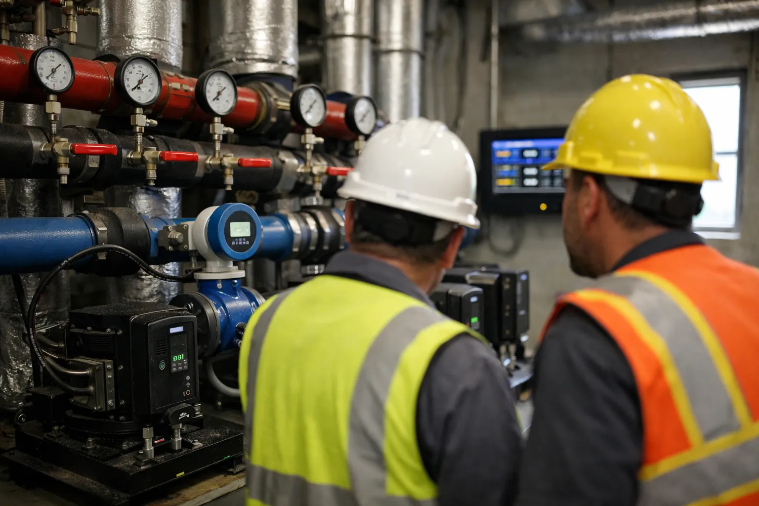
Converting a legacy two‑pipe hydronic system to a four‑pipe distribution is one of the most effective retrofits to enable simultaneous heating and cooling, improve tenant comfort, and prepare a building for heat‑pump or hybrid plant integration. This guide walks an HVAC enthusiast or engineer through the practical steps—assessment, design decisions, equipment selection, piping and valve practices, controls, commissioning and common failure modes—so you can plan and execute a successful mid‑rise conversion in 2026 and beyond.
Why convert: benefits and when it makes sense
- Simultaneous heating and cooling per floor or zone—eliminates morning/evening changeover limitations of two‑pipe systems.
- Supports diverse tenant needs and mixed uses (offices, meeting rooms, server closets) without complex plumbing workarounds.
- Enables plant upgrades (central chillers + boilers, heat pumps, or hybrid plants) without full terminal replacement.
- Improves occupant comfort and reduces tenant complaints that can arise from seasonal lag in two‑pipe systems.
High‑level conversion strategies (choose one by building constraints)
There are three common approaches—select based on budget, available vertical space, and acceptable disruption:
- Full riser conversion: Install dedicated hot and chilled water risers (four‑pipe main and returns) serving existing terminals that are reconfigured to accept both fluids. Best long‑term but highest disruption and cost.
- Parallel terminal conversion (fan‑coil or FCUs): Leave the two‑pipe distribution in place initially and add fan‑coil units connected to new four‑pipe mains on each floor. Lower riser work, moderate disruption, good for phased projects.
- Hybrid heat‑exchanger approach: Run small-diameter secondary loops (plate heat exchangers) at floors or zones that decouple existing two‑pipe circuits from the new plant. Useful where riser space is limited.
Step 1 — Building assessment and documentation
Before design, compile the following:
- As‑built piping riser drawings, mezzanine mechanical room layout, and access points.
- Terminal types and conditions (radiators, convectors, fan coils, induction units), heat emitter capacities, and hydraulic characteristics.
- Existing plant data: boiler and chiller capacities, pump curves, expansion tanks and glycol content, control schematics and BAS compatibility.
- Peak loads by zone / floor (heating and cooling). If unavailable, perform room‑by‑room load estimate or use building‑type rules (e.g., 15–30 Btu/ft2 for offices) and confirm with spot measurements.
Example assessment (for illustration)
Mid‑rise office, 8 stories, 100,000 ft2. Existing two‑pipe system serves perimeter radiators and interior fan coils. Estimated peak simultaneous heat/cool capacity needed after conversion: 800,000 Btu/h. This drives pipe sizes, pump capacity and control strategy.
Step 2 — Hydronic design basics and sample calculations
Key design variables: design ΔT, required flow (GPM), pipe sizing, pump head, and component selection.
- Use the standard formula to convert load to flow: GPM = Load (Btu/h) / (500 × ΔT). Example: With 800,000 Btu/h peak and ΔT = 20°F → GPM = 800,000 / (500×20) = 80 GPM.
- Select design ΔT consistent with equipment: 10–20°F is common for office fan coils; higher ΔT reduces pipe sizes but may increase pump energy and cause comfort control issues.
- Estimate pump head by summing riser and floor distribution losses, terminal pressure drop and isolation valves. Use manufacturer curves and include a 10–20% safety margin.
Step 3 — Piping layout and materials
Best practices for mid‑rise four‑pipe conversion:
- Run hot and chilled water supply and return risers in parallel stacks to limit mixing and facilitate isolation. Keep same riser pipe sizes as required by flow.
- Use welded steel or carbon steel for risers where building code allows, and copper or PEX‑a with approved fittings for horizontal branch runs where accessible. Consider brazed stainless for high‑corrosion risk areas.
- Insulate chilled water piping fully to ASHRAE/IECC requirements to prevent condensation. Insulate hot water where energy code requires.
- Provide sectioning/isolation valves at every floor and branch to allow phased commissioning and maintenance.
Step 4 — Terminal modifications and valve strategy
Terminals originally sized for two‑pipe operation need evaluation. Options include reuse with modification or replacement:
- Install 4‑port diverter manifolds or changeover valves at terminals only if space and piping allow. Avoid three‑way valves unless necessary—two‑way valves with PICVs (pressure‑independent control valves) are preferred for modern BAS control and better ΔT maintenance.
- When adding FCUs, select units with factory‑installed pump circuits or easy hydronic connections. Verify coil face area for desired ΔT and airflow.
- Install balancing valves or PICVs at each terminal to ensure guaranteed flow and to simplify commissioning.
Step 5 — Pumping, hydraulics and controls
- Use primary/secondary pumping for larger plants: primary pumps maintain plant ΔT and secondary pumps serve distribution risers. VFDs on distribution pumps let you control flow to match loads and reduce energy consumption.
- Install bypass or variable primary loops where plant and distribution systems would otherwise cause low valve authority. Avoid deadheading pumps—use pressure sensors and VFDs for reliable control.
- Integrate pumps and valves into the building automation system (BACnet/IP or Modbus). Provide key points: pump speed command, motor amps, flow meters (magnetic or ultrasonic), supply and return temperatures, and valve positions.
Step 6 — Controls sequence and BAS integration
Design a clear sequence of operations:
- Control precedence: plant‑level setpoints (supply temp) should coordinate with distribution setpoints; prevent fighting between boilers/chillers and terminal valves.
- Cooling and heating isolation: where terminals can see hot and chilled water simultaneously, ensure interlocks to avoid short‑cycling. Use differential setpoints or enable both only when needed by zone demand.
- Implement demand limiting and plant staging tied to BAS energy meters and outdoor reset. Incorporate fault detection for low ΔT, pump cavitation, or valve failures.
Step 7 — Phased execution and minimizing tenant impact
A phased approach reduces disruption and limits downtime:
- Phase by floor: isolate one floor at a time, install new four‑pipe headers, and switch floor terminals to the new system during off‑hours.
- Use temporary heaters or portable AC during changeover for tenant comfort where necessary.
- Schedule tie‑ins strategically: use weekends for riser taps and overnight for valve changes to minimize business impacts.
Step 8 — Commissioning checklist (must‑do tests)
Thorough commissioning ensures performance and avoids callbacks. Minimum tests:
- Hydrostatic pressure test of new piping per code; check for leaks and repair before insulation.
- Flow verification: measure GPM at representative riser branches and terminals. Compare to design flows (use clamp‑on ultrasonic flow meters or calibrated rotameters).
- ΔT verification: measure supply and return temperatures at plant and at representative terminals at design flow and reduced loads. Expect designed ΔT (±10%).
- Valve and actuator stroke tests, end‑to‑end BAS point validation and alarm verification.
- Energy checks: pump power vs. expected kW at different speeds; VFD operation and soft‑start verification.
Common pitfalls and how to avoid them
- Insufficient valve authority: use PICVs and proper pressure control to avoid unstable flows and poor ΔT.
- Poor labeling and documentation during phased work—maintain a live as‑built and update BAS point lists.
- Neglecting air management: install automatic air separators and vents on each floor; purge thoroughly during commissioning.
- Ignoring thermal expansion and routing restraints: provide loops and expansion joints in long risers; verify support spacing per code.
- Under‑sized pumps due to optimistic head estimates—use measured existing pump curves if available, and model the system before procurement.
Cost drivers and rough timeline
Costs vary widely by building complexity and scope. Major drivers are:
- Amount of vertical riser work and shaft penetrations.
- Terminal modifications or replacements (fan coils, converters).
- BAS and control upgrades.
- Phasing requirements that extend labor time.
A realistic schedule for an 8‑story mid‑rise: 3–6 months design and permitting; 4–9 months construction (phased), depending on crew size and tenant coordination.
Preparing for future upgrades
Design the four‑pipe distribution with future electrification and heat‑pump integration in mind:
- Reserve space and provide stub‑ups in mechanical rooms for future heat pump modules or electric chillers.
- Specify BAS points and wiring for future sensors (flow, pipe temperature, energy meters).
- Choose materials compatible with variable water temperatures and glycol if freeze protection will be used for heat pump operation.
Final checklist before turnover
- Complete as‑built drawings and wiring diagrams uploaded to the BAS and facility management system.
- All commissioning data logged and handed to owner: flow reports, ΔT charts, pump curves and VFD parameters.
- Operator training: walk grounds and mechanical rooms with facility staff, run manual and automatic sequences, and show troubleshooting steps.
- Maintenance plan: specify valve exercise schedules, strainer cleaning intervals, and periodic balancing verification.
Converting a two‑pipe system to four‑pipe in a mid‑rise building is a major but highly impactful retrofit. With careful assessment, a phased execution plan, attention to hydraulic details (ΔT, pump sizing, valve authority), and rigorous commissioning tied into a modern BAS, owners gain tenant comfort, operational flexibility and a platform for future decarbonization. Use this field guide as a checklist and working framework; adapt specifics to your project's constraints, local codes and the latest manufacturer guidance in 2026.