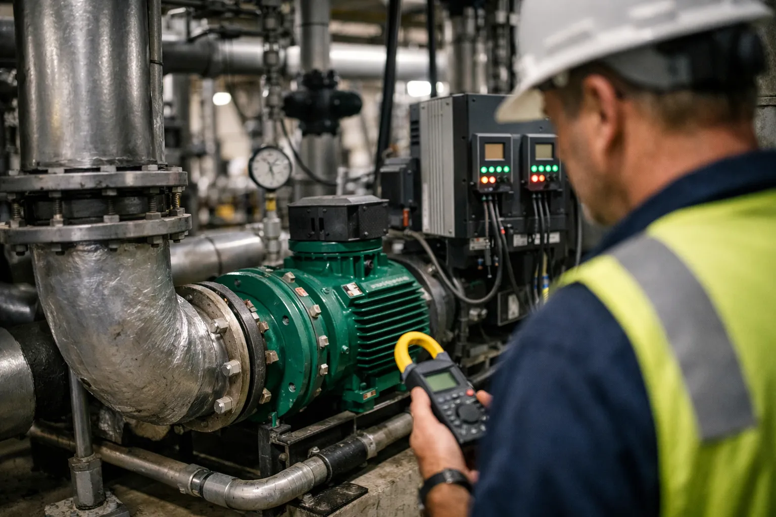
Converting a constant‑flow chilled‑water plant to variable‑flow pumping is one of the most cost‑effective upgrades building owners and engineers can make. When done right, variable‑flow pumping reduces pump energy dramatically, improves system responsiveness, and can simplify balancing. Done poorly, it creates low ΔT, control instability, or even equipment damage. This guide walks HVAC enthusiasts and practitioners through a practical, step‑by‑step conversion process for 2026‑era plants, with specific checks, controller logic, commissioning tests, and traps to avoid.
Why variable‑flow matters (quick engineering recap)
Pump power scales roughly with the cube of flow according to the affinity laws. Cutting system flow by 20% can reduce pump power by roughly half. In many chilled‑water plants, pumps account for 10–25% of HVAC electrical demand; variable flow typically yields 30–70% pump energy savings depending on load profile. Beyond energy, variable pumping can reduce mechanical wear, improve temperature control when combined with modern controls, and simplify seasonal operation.
Before you start: assessment and constraints
Do a thorough pre‑conversion assessment. Key items to collect:
- As‑built piping and instrument drawings (P&IDs) and single‑line diagrams
- Pump curves, motor nameplate data, and VFD compatibility
- Chiller manufacturer guidance on minimum evaporator flow and turndown limits
- Existing control sequences in the BAS/PLC and I/O list
- Historic DDC trends for leaving/entering chilled‑water temps, flows (if metered), loop ΔT, and pump run hours
- Cooling tower and condenser‑side pump information for water‑cooled chillers (if applicable)
Critical red flags that may require additional work before conversion:
- Chillers with explicit manufacturer prohibitions against variable evaporator flow or minimum flow >20% of design.
- Extensive hydronic distribution with multiple manual balancing valves sized for constant flow—those may need removal or re‑balancing.
- Existing chilled‑water temperature control that measures only supply temperature at the plant, not return or zone temps—upgrade sensing recommended.
Design decisions and control architecture
Choose a pumping topology and control approach. The common architectures:
- Primary‑secondary (existing constant‑flow): Keep chiller evaporator primary pumps constant, add VFDs on secondary distribution pumps to modulate flow to the building. This is the least risky retrofit when chillers expect constant primary flow.
- Variable‑primary (VP): Make chilled‑water pumps feeding chiller evaporators variable. This reduces pump count and piping complexity but requires confirmation of chiller minimum flow and more advanced controls.
- Primary‑variable (PV) or variable‑primary/variable‑secondary hybrids: A middle ground—one set of pumps variable, others modulated for distribution. Requires careful control sequencing.
For retrofit projects in 2026, many facilities prefer primary‑secondary with VFDs on secondary pumps as a conservative step, then evaluate migrating to true variable‑primary in a later phase after confirming chiller vendor acceptability and operational data.
Control strategies — practical options
- ΔP (differential pressure) reset: Install a differential pressure transducer on the main supply/return and reset the setpoint based on expected system load or supply temperature. Use this for distribution pumps to provide just enough head to operate terminal devices without overpumping.
- ΔT (temperature) recovery control: Monitor leaving and entering chilled‑water temperatures; if ΔT collapses below a threshold, reduce flow or stage additional chillers/pumps. This combats low‑ΔT syndrome and ensures efficient chiller operation.
- Flow control with flow meters: Where critical terminal units require guaranteed flow, use flow meters and PID flow control loops rather than pressure control alone.
- Sequencing and anti‑short‑cycling: Implement minimum run times and lockouts in BAS for pumps and chillers to prevent wear from frequent starts/stops as flow varies.
Equipment selection: VFDs, sensors, and protection
Key selection criteria:
- VFDs: Choose VFDs sized to motor full‑load amps plus margin. Prefer drives with built‑in motor protection, harmonic mitigation options (or plan external filters if site sensitive), and fieldbus support (BACnet/IP, Modbus, or native BAS integration).
- Sensors: Install a high‑accuracy differential pressure transducer on the chilled‑water main for ΔP control; place supply and return temperature sensors near main headers for ΔT monitoring. Use 0.1°C (0.2°F) capable sensors for tight control.
- Flow meters: If the application demands, install clamp‑on ultrasonic or insertion flow meters for verification and closed‑loop flow control. Clamp‑on units are non‑intrusive for retrofit but verify accuracy at low flow.
- Minimum flow bypass: Provide a controlled bypass or minimum flow recirculation loop for chillers that require guaranteed evaporator flow. Use a modulating valve or a small bypass pump with interlocks.
Installation and integration checklist
- Install VFDs and ensure appropriate wiring, grounding, and electrical coordination (short‑circuit ratings, fused disconnects).
- Mount pressure and temperature sensors at recommended straight‑run distances; install thermowells if required.
- Remove unnecessary manual throttling (if converting constant‑flow by using balancing valves) and rework balancing infrastructure where practical.
- Integrate VFD control points into the BAS: speed command, run/stop, fault status, actual current/power, and alarms.
- Implement mechanical protections: soft starters for large motors during commissioning, vibration monitoring, and ensure pump shafts/couplings aligned.
Commissioning: practical, step‑by‑step tests
Commissioning is where the project succeeds or fails. Use a structured sequence and log everything.
- Baseline logging: Run and log the system under typical conditions before changeover if possible. Capture supply/return temps, pump currents, and building loads.
- Pump curve verification: At multiple speeds, measure flow (or infer from valve authority) and motor current; compare to pump curves. Confirm VFD speed vs flow behavior.
- Minimum flow verification: Confirm chiller manufacturer minimum evaporator flow is maintained at all operating points. Adjust bypass as needed.
- ΔP control tuning: Start with a conservative ΔP setpoint (near design head) and slowly implement reset schedule while tuning PID gains. Log stability and valve/actuator travel.
- ΔT validation: At several load points (high, medium, low), measure chilled‑water ΔT across coils and chiller evaporators. Validate that ΔT does not collapse below acceptable thresholds (common design target: ~5.6°C/10°F, with plant‑specific tolerances).
- Sequence failure modes: Simulate fault conditions—pump trip, VFD fault, sensor failure—to ensure safe fallback states (e.g., lock pumps on, open bypass, alarm BAS).
- Long‑run stability test: Run the system over at least a 24–72 hour period, covering diurnal load swings. Analyze trends for hunting, hunting‑induced valve wear, or unexpected chilled‑water temperature drift.
Data logging and acceptance criteria
Define acceptance metrics up front. Typical criteria include:
- Stable ΔP control with minimal hunting (verified by trend files)
- ΔT within acceptable range at design and part‑load conditions
- Pump current consistent with expected energy savings (use affinity law estimates)
- System returns to safe condition on faults
- Interlocks and BAS alarms validated
Collect trend data at 1–5 minute intervals for acceptance tests and keep logs for seasonal tuning adjustments.
Common pitfalls and troubleshooting
- Low ΔT syndrome: After conversion, many systems see ΔT collapse because flow increases to meet thermal load or because terminal valves were previously set wide for constant flow. Address with ΔT‑based sequencing, flow recapture strategies, and terminal rebalancing.
- Chiller hunting or nuisance trips: Insufficient minimum flow or overly aggressive VFD ramps can destabilize chillers. Respect vendor minimum flow and set safe acceleration/deceleration ramps.
- Sensor placement errors: Poorly located ΔP or temperature sensors give misleading control inputs—place them per best practice, away from deadlegs and with proper immersion sleeves.
- Harmonics and electrical issues: Large VFD installs may require harmonic mitigation or transformer adjustments; watch for motor overheating and neutral currents.
- Valve authority and actuator wear: When throttling is removed, some actuators may never travel fully. Reprogram actuator calibration and remove strain from over‑travel.
Operational tuning and continuous optimization
Post‑acceptance, plan a 3‑month tuning period. Use logged data to:
- Refine ΔP reset curves to match seasonal load shape
- Implement ΔT recovery logic if terminal units are starving—e.g., temporarily increase head when ΔT drops below setpoint
- Adjust VFD start/stop scheduling to align with building occupancy and chiller staging
- Consider retrofit of additional VFDs for condenser pumps and cooling tower fans where feasible to compound savings
Economics and payback—an illustrative example
Example: a 30 kW distribution pump running 4,000 hours/year at $0.12/kWh costs roughly $14,400/year. If the conversion reduces average pump power by 40% (typical in many applications), annual savings ≈ $5,760. If installed cost (VFD, wiring, controls engineering) is $12,000, simple payback ≈ 2.1 years. Real projects should include commissioning, BAS integration, and contingency in the cost model.
Final checklist before handover
- As‑built updates to P&ID and BAS points
- Commissioning report with trend logs and acceptance criteria
- Operator training on VFD and BAS interactions, including emergency manual overrides
- Maintenance plan for VFDs (filters, fans, firmware) and periodic re‑balancing checks
- Performance monitoring plan with key performance indicators (ΔT, pump energy, flow, alarms)
Converting a constant‑flow chilled‑water plant to variable‑flow pumping delivers strong energy savings and operational benefits but requires careful hydraulic review, manufacturer coordination, and robust controls and commissioning. Follow the steps above—assess constraints, pick an architecture, spec reliable VFDs and sensors, tune and validate rigorously—and you’ll avoid the common failure modes and capture the benefits reliably.